Safe needle guard and safe blood taking needle cylinder
A safe, needle sheath technology, applied in the direction of needles, blood sampling devices, medical science, etc., can solve the problems of reducing the work efficiency, time-consuming and troublesome of medical staff
- Summary
- Abstract
- Description
- Claims
- Application Information
AI Technical Summary
Problems solved by technology
Method used
Image

Examples
Embodiment 1
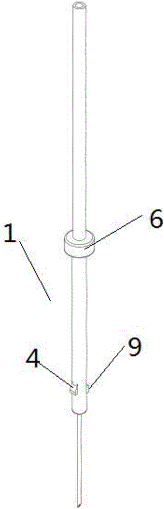
[0032] Such as figure 1 , 2 As shown in and 3, a safety needle cover described in this embodiment includes a needle body 1, and the protective sheath 2 sleeved on the needle body 1 is rotated through a connecting structure, and the connecting structure includes at least one The chute 3 on the protective cover 2, at least one sliding part 4 provided on the needle body 1 and slidably embedded in the chute 3; wherein, the tail end of the chute 3 is also provided with at least one elastic The blocking part 5, when recovering, the needle head of the needle body 1 retracts toward the inner cavity of the protective sheath 2 or the protective sheath 2 slides toward the needle head of the needle body 1, when the sliding part 4 passes over the The elastic blocking part 5, the needle is retracted into the inner cavity of the protective sheath 2; as a preferred embodiment, the protective sheath 2 is set as a butterfly-shaped protective sheath 2
[0033] In this safety needle cover, the ...
Embodiment 2
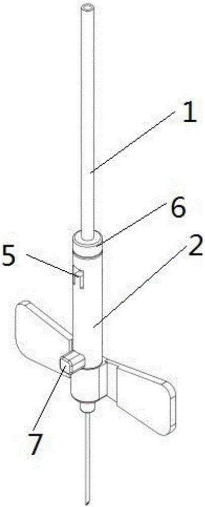
[0038] Such as Figure 4 and 5As shown, a safety needle sheath described in this embodiment includes a needle body 1, and a protective sheath 2 sleeved on the needle body 1 is rotated through a connection structure, and the connection structure includes at least one 2, at least one sliding part 4 provided on the needle body 1 and slidably embedded in the sliding groove 3; wherein, the tail end of the sliding groove 3 is also provided with at least one elastic blocking part 5. When recovering, the needle head of the needle body 1 retracts toward the inner cavity of the protective sheath 2 or the protective sheath 2 slides toward the needle head of the needle body 1. When the sliding part 4 passes over the elastic The blocking part 5, the needle is retracted into the inner cavity of the protective sheath 2; as a preferred embodiment, the protective sheath 2 is set as a butterfly-shaped protective sheath 2.
[0039] In this safety needle cover, the sliding part 4 of the needle ...
Embodiment 3
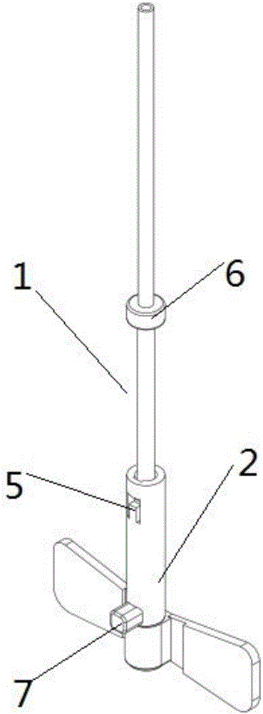
[0044] Such as Figure 6 and 7 As shown, as a convertible embodiment, the difference between this embodiment and Embodiment 2 is that the elastic blocking part 5 is set as two inverted tooth elastic blocking parts formed on the inner side wall of the tail end of the through groove. .
PUM
 Abstract
Description
Claims
Application Information