Supercharge Your Innovation With Domain-Expert AI Agents!

Quantity-controllable batch feeder

A feeder and feeding device technology, which is applied to feed, mixer, mixer accessories, etc., can solve the problems of low efficiency, less theoretical research, unevenness, etc., to prevent material overhead and uneven distribution, and control the feeding amount. Feeding effect

Active Publication Date: 2017-02-22
SHANDONG UNIV OF TECH
View PDF4 Cites 0 Cited by
  • Summary
  • Abstract
  • Description
  • Claims
  • Application Information

AI Technical Summary

Problems solved by technology

[0002] In the 1960s, TMR feeding technology was first promoted experimentally in Britain, the United States, Israel and other western countries. Practice has proved that TMR feeding technology can effectively promote the development of animal husbandry. However, as a country with large dairy cows, my country’s theoretical research on TMR feeding technology Fewer, among which, as an important component of the supporting technology of the TMR feeding process, the research and development of the feeding device is very little
The main working principle of the existing feeding device is to use the conveyor belt to convey the material. Although the labor saving has been realized, the situation of the material forming agglomerates and lumps after the mixing is still unresolved, and there are problems such as insufficient feeding uniformity and low efficiency. It leads to incomplete, uneven and unhygienic feeding of dairy cows, which seriously restricts the development of animal husbandry in my country

Method used


Image

  • Quantity-controllable batch feeder
  • Quantity-controllable batch feeder
  • Quantity-controllable batch feeder

Examples


Embodiment Construction

[0012] The present invention will be described in further detail below in conjunction with the embodiments given by the accompanying drawings.

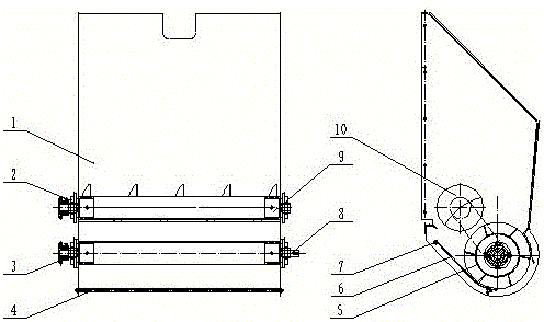
[0013] refer to figure 1 The invention discloses a controllable amount feeding device suitable for being installed on a TMR feed mixer, belonging to the technical field of agricultural machinery. Material door upper shield 1, bearing with seat 2, gear 3, hinge pin (1) 4, discharge mechanism 5, discharge tongue 6, hinge pin (2) 7, long shaft head 8, short shaft head 9, even The material auger 10 is characterized in that: the upper shield 1 of the material door is fixedly connected to the material door of the TMR feed mixer, and the even material auger 10 is connected and installed with the bearing 2 through a long shaft head 8 and a short shaft head 9 At the discharge port, the upper end of the discharge tongue 6 is hinged to the upper shield side plate of the material door through the hinge (2) 7, and the lower end of the discharge t...


PUM


Abstract

The invention relates to a quantity-controllable batch feeder mounted on a TMR feed mixer and belongs to the technical field of agricultural machinery. The batch feeder comprises a feed door upper shield, a mounted bearing, a gear, a hinge pin (1), a discharging mechanism, a discharging tongue, a hinge pin (2), long shaft heads, short shaft heads and a mixing screw conveyor. The batch feeder is characterized in that the feed door upper shield is fixedly connected to a feed door, the mixing screw conveyor is connected with the mounted bearing through the long shaft heads and the short shaft heads to be mounted at a discharging port, the upper end of the discharging tongue is hinged to a side plate of the feed door upper shield through the hinge pin (2), the lower end of the discharging tongue is placed on the hinge pin (1) with three adjusting positions, the discharging mechanism is connected with the mounted bearing through two long shaft heads to be mounted below the discharging port and forms a certain gap with the discharging tongue, and the long shaft heads on the same side are connected through a gear chain to transfer power. The batch feeder can realize quantity-controllable uniform batch feeding.

Description

technical field [0001] The invention relates to a controllable feeding device suitable for being installed on a TMR feed mixer, belonging to the technical field of agricultural machinery. Background technique [0002] In the 1960s, TMR feeding technology was first promoted experimentally in Britain, the United States, Israel and other western countries. Practice has proved that TMR feeding technology can effectively promote the development of animal husbandry. However, as a country with large dairy cows, my country’s theoretical research on TMR feeding technology Fewer, among which, as an important component of the supporting technology of the TMR feeding process, the research and development of the feeding device is very little. The main working principle of the existing feeding device is to use the conveyor belt to convey the material. Although the labor saving has been realized, the situation of the material forming agglomerates and lumps after the mixing is still unresolv...

Claims


Application Information

Patent Timeline
IPC IPC(8): B01F15/02B01F15/04A23N17/00
CPCA23N17/00B01F35/75455B01F35/79B01F2101/18
Inventor 李其昀高冠宝程修沛
Owner SHANDONG UNIV OF TECH
Features
  • R&D
  • Intellectual Property
  • Life Sciences
  • Materials
  • Tech Scout
  • Unparalleled Data Quality
  • Higher Quality Content
  • 60% Fewer Hallucinations
Learn More