Ejector with spray nozzle position adjustable and device

A technology of injectors and nozzles, applied in the direction of injection devices, liquid injection devices, etc., can solve problems such as the decline in the efficiency of injectors, and achieve the effect of improving performance and good performance

Inactive Publication Date: 2017-02-22
SHANDONG UNIV
View PDF5 Cites 19 Cited by
  • Summary
  • Abstract
  • Description
  • Claims
  • Application Information

AI Technical Summary

Problems solved by technology

[0005] In order to solve the shortcomings of the prior art, the present invention provides an injector and device with adjustable nozzle posi

Method used


Image

  • Ejector with spray nozzle position adjustable and device
  • Ejector with spray nozzle position adjustable and device

Examples


Embodiment Construction

[0029] Below in conjunction with accompanying drawing and embodiment the present invention will be further described:

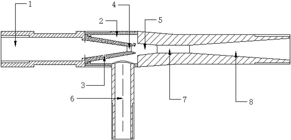
[0030] figure 1 Structural diagram of a traditional injector. Such as figure 1 The structure of the conventional injector shown is:

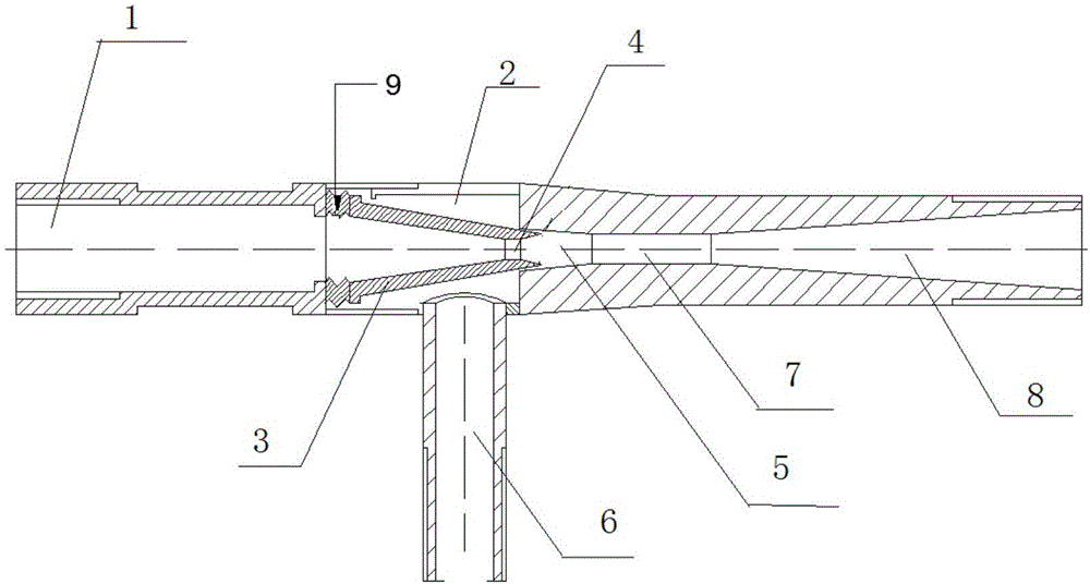
[0031] The injector includes a primary flow pipe 1, a nozzle 3, a receiving chamber 2, a secondary flow pipe 6, a mixing chamber and a diffusion chamber 8; wherein, the mixing chamber includes two mixing sections, namely an equal pressure mixing section 5 and an equal area mixing section 7.

[0032] The nozzle 3 is connected to the outlet of the primary flow pipe 1, and the nozzle 3 crosses the receiving chamber 2 and enters the mixing chamber; the diffusion chamber 8 is connected to the outlet of the mixing chamber; the secondary flow pipe 6 is placed in the mixing chamber Below, into the mixing chamber.

[0033] How the injector works:

[0034] The primary stream steam (that is, power steam) enters the nozzle 3 for adia...


PUM


Abstract

The invention discloses an ejector with a spray nozzle position adjustable and a device. The ejector with the spray nozzle position adjustable comprises a primary flow tube, a spray nozzle, a receiving chamber, a secondary flow tube, a blending chamber and a diffusion chamber. An expansion device with the length varying along variation of pressure is arranged at the joint of the primary flow tube and the spray nozzle. The primary flow tube, the expansion device, the spray nozzle, the blending chamber and the diffusion chamber are sequentially connected along the axis. The spray nozzle position of the ejector is automatically adjusted simply through variation of the flow rate of primary flow, the performance of the ejector is changed accordingly, and the ejector can have good performance under different working conditions.

Description

technical field [0001] The invention belongs to the field of injectors, in particular to an injector and a device with adjustable nozzle positions. Background technique [0002] Ejector is a widely used fluid machine, which uses the jet of working fluid to realize energy conversion. Because of its simple structure, low cost and convenient operation and maintenance, the ejector is widely used in the fields of gas extraction, waste heat recovery and mixed heating. [0003] Ejectors rely on mutual collisions between fluids to transfer energy, and the internal mixing process is very complicated, so empirical formulas are mostly used in the research on injectors. In recent years, more and more attention has been paid to the simulation experiment of using CFD software to simulate the fluid flow inside the injector. However, due to the difficulty of experimentation, relatively little is known about the flow of fluid inside the injector. [0004] Due to the above reasons, the cur...

Claims


Application Information

Patent Timeline
IPC IPC(8): B05B7/04B05B15/08B05B15/68
CPCB05B7/0408B05B15/68
Inventor 王雷贾丰泽赵红霞
Owner SHANDONG UNIV
Why Eureka
Try Eureka