Supercharge Your Innovation With Domain-Expert AI Agents!

A needle control device capable of adjusting the nozzle area of ​​the injector and the injector

A nozzle area, control device technology, applied in the direction of spraying device, spraying device, etc., can solve the problems of poor environmental adaptability, complex control system, bulky stepping motor, etc., and achieve the effect of improving performance and good performance

Active Publication Date: 2018-06-12
青岛氢阳智能装备有限公司
View PDF7 Cites 0 Cited by
  • Summary
  • Abstract
  • Description
  • Claims
  • Application Information

AI Technical Summary

Problems solved by technology

Due to the large size of the stepper motor, poor environmental adaptability and complex control system, it has not been widely used.

Method used


Image

  • A needle control device capable of adjusting the nozzle area of ​​the injector and the injector
  • A needle control device capable of adjusting the nozzle area of ​​the injector and the injector
  • A needle control device capable of adjusting the nozzle area of ​​the injector and the injector

Examples


Embodiment 1

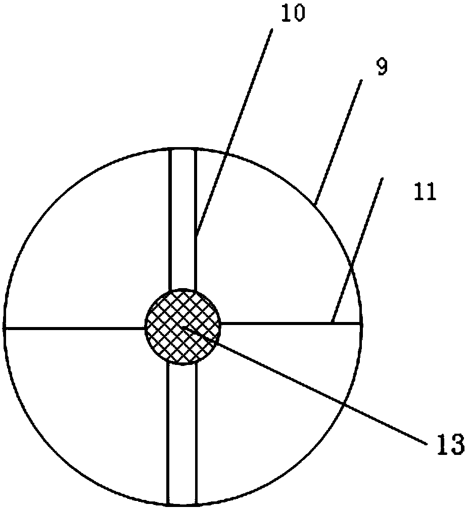
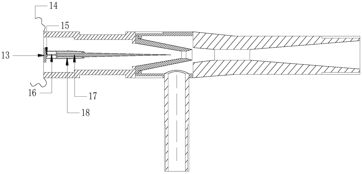
[0052] Such as image 3 and Figure 7 As shown, the needle motion control device includes: a heating resistor 15 arranged inside the needle support tube 18 and connected to a fixed bracket, the heating resistor 15 is connected to the injection needle 17 through a material 16 that expands with heat and contracts with cold; the heating wire of the heating resistor 15 14 is drawn out through the hollow beam 10 of the fixed support;

[0053] Power is supplied to the heating resistor 15 through wires, and the temperature of the resistor is changed by changing the power supply current or voltage. The thermal expansion and contraction material 16 will be deformed due to the principle of thermal expansion and contraction, thereby driving the needle 17 to move.

[0054] The thermal expansion and contraction material 16 is heated by the heating resistor 15, so that the thermal expansion and contraction material 16 is deformed to control the movement of the needle 17 to a position close...

Embodiment 2

[0059] Such as Figure 4 and Figure 8 As shown, the needle motion control device includes: an electromagnet 19 arranged inside the needle support tube 18 and connected to the fixed bracket, a permanent magnet 22 is arranged at the end of the needle 17 near the end of the fixed bracket, and the electromagnet 19 passes through the spring 21 Connect with the permanent magnet 22; the energized wire 20 connected with the electromagnet 19 is drawn out through the hollow beam 10 of the fixed bracket; by changing the magnitude of the current of the electromagnet 19, the electromagnet 19 and the permanent magnet 22 act to control the movement of the spray needle 17; When the electromagnet 19 is not energized, that is, when the spring 21 is not deformed, the position of the spray needle 17 is the initial position. When passing a current to the electromagnet 19 to generate a repulsive force between it and the permanent magnet 22, control the needle 17 to move to the right to reach the ...

Embodiment 3

[0063] Such as Figure 5 and Figure 9 As shown, the needle motion control device includes: a sealing piston 24 is arranged inside the needle support tube 18, a cavity 30 is provided between the sealing piston 24 and the fixed bracket, and the sealing piston 24 is connected with the injection needle 17; The hollow beam 10 leads out the fluid introduction pipe 23, and the fluid introduction pipe 23 communicates with the cavity 30 through the fluid introduction port 25;

[0064] The fluid is introduced or extracted into the cavity 30 through the fluid introduction tube 23. According to the volume of the fluid introduced or extracted, when the fluid is extracted, the pressure in the cavity 30 decreases, the piston 24 drives the injection needle 17 to move to the left, and the piston 24 drives the injection needle. 17 moves to the left; when the fluid is injected, the pressure in the cavity 30 increases, pushing the piston 24 to move to the right, and the piston 24 drives the spr...


PUM


Abstract

The invention discloses a needle control device capable of adjusting the area of an ejector nozzle and an ejector. The needle control device comprises a needle arranged in a primary flow pipe and on the axis of the throat portion of the nozzle, and a fixed support fixed to the pipe wall of the primary flow pipe. The needle is connected with the fixed support through a needle supporting pipe. One end of a needle movement control device is fixed to the fixed support, the other end of the needle movement control device is connected with the needle, the needle movement control device is used for controlling movements of the needle, and accordingly the area of the throat of the ejector nozzle is changed. The needle control device has the advantages that the area of the throat portion of the ejector can be adjusted online, the performance of the ejector is improved, and the ejector has good performance under different working conditions.

Description

technical field [0001] The invention relates to the technical field of injectors, in particular to a needle control device capable of adjusting the nozzle area of ​​the injector and the injector. Background technique [0002] Ejector is a widely used fluid machine, which uses the jet of working fluid to realize energy conversion. Because of its simple structure, low cost and convenient operation and maintenance, the ejector is widely used in the fields of gas extraction, waste heat recovery and mixed heating. [0003] Ejectors rely on mutual collisions between fluids to transfer energy, and the internal mixing process is very complicated, so empirical formulas are mostly used in the research on injectors. In recent years, more and more attention has been paid to the simulation experiment of using CFD software to simulate the fluid flow inside the injector. However, due to the difficulty of experimentation, relatively little is known about the flow of fluid inside the injec...

Claims


Application Information

Patent Timeline
Patent Type & Authority Patents(China)
IPC IPC(8): B05B1/26
CPCB05B1/26
Inventor 王雷贾丰泽赵红霞
Owner 青岛氢阳智能装备有限公司
Features
  • R&D
  • Intellectual Property
  • Life Sciences
  • Materials
  • Tech Scout
  • Unparalleled Data Quality
  • Higher Quality Content
  • 60% Fewer Hallucinations
Learn More