Hole inner wall chamfering and punching device and method thereof

A technology of hole inner wall and chamfering, which is applied in the field of hole inner wall chamfering and punching equipment, which can solve problems such as chamfering deviation, achieve the effect of eliminating quality hidden dangers and ensuring product quality and consistency

Active Publication Date: 2017-02-22
沈阳兴华航空电器有限责任公司
View PDF7 Cites 2 Cited by
  • Summary
  • Abstract
  • Description
  • Claims
  • Application Information

AI Technical Summary

Problems solved by technology

Solve the problem of chamfer deviation in the three holes on the side wall of the square plate, and ensure the verticality and consistency of the chamfer on the inner wall

Method used


Image

  • Hole inner wall chamfering and punching device and method thereof
  • Hole inner wall chamfering and punching device and method thereof
  • Hole inner wall chamfering and punching device and method thereof

Examples


Embodiment 1

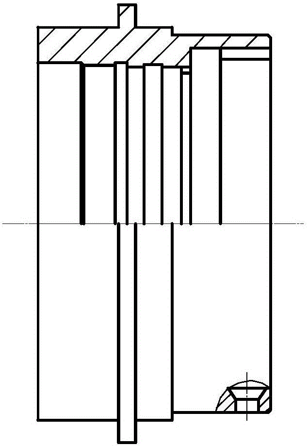
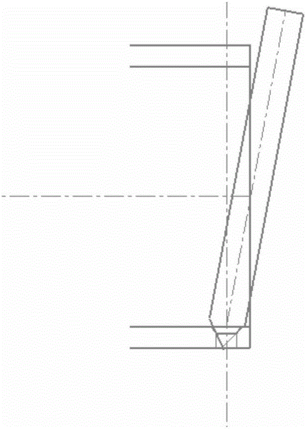
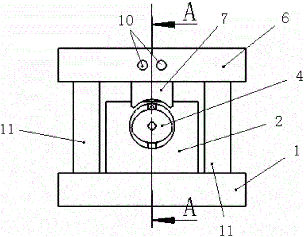
[0027] The hole inner wall side chamfering punching device is composed as follows: the hole inner wall chamfering punching device is composed as follows: lower fixing plate 1, inserting plate 2, lower punch 3, pillar 4, first pin 5, upper fixing plate 6 , the upper punch 7, the second pin 8, the bolt 9, the third pin 10 and the guide post 11; wherein, the pillar 4 is a columnar structure with an asymmetrical ellipse in section, and the two semi-arc contact ends of the asymmetrical ellipse There is an R5 chamfer structure 43, the pillar 4 includes an axial step through hole 41 and a first radial through hole 42, the axial step through hole 41 and the first radial through hole 42 communicate through each other, and one end of the lower punch 3 is connected to the The conical point structure 31 with the chamfering of the side wall of the punched part matches, the middle part of the lower punch 3 is provided with a second radial through hole 32, and one end of the conical point str...


PUM


Abstract

The invention discloses a hole inner wall chamfering and punching device and a method thereof. The hole inner wall chamfering and punching device is composed of a lower fixing plate (1), an inserting plate (2), a lower punch (3), a supporting column (4), a first pin (5), an upper fixing plate (6), an upper punch (7), a second pin (8), a bolt (9), a third pin (10) and a guide column (11). The supporting column (4) is of a columnar structure with the section being an asymmetrical oval. The hole inner wall chamfering and punching method is a rapid and consistent machining method for a hole wall inner chamfering structural element, the problem that inner chamfering is oblique due to previous drilling machining of bench workers is solved, and the hole inner wall chamfering and punching method is especially important to the aspects of ensuring the machining quality of part inner chamfering, meeting the requirements of bayonet lock rivet force and improving the quality stability of products and has an important application value in machining of other similar part structures.

Description

technical field [0001] The invention relates to the technical field of chamfering punching methods, and in particular provides a hole inner wall chamfering punching device and a method thereof. Background technique [0002] A large number of housings in the connector have the processing technology of chamfering in the three horizontal holes of the housing cavity. Due to the limited space of the inner wall, the chamfering process is performed by drilling, so that the chamfering is deflected. For example, the inner cavity is φ21 .79mm shell, drilled on the φ21.79 cavity with a φ3 70° drill bit, the deviation is 10.44°, the simulation is shown in the appendix figure 2 . The smaller the inner cavity, the more serious the deviation. The chamfered part is used for riveting bayonet pins. Due to the deflection of the chamfers, it is easy to cause unreliable riveting, the riveting force is unqualified, and there are quality risks. [0003] People are eager to obtain a hole inner w...

Claims


Application Information

Patent Timeline
Patent Type & Authority Applications(China)
IPC IPC(8): B21D19/08B23P15/00
CPCB21D19/08B23P15/00
Inventor 庞金红刘冬南艳明
Owner 沈阳兴华航空电器有限责任公司
Why Eureka
Try Eureka