
Rotary sandblasting workbench for rotary vibration screen frame and bottom barrel workpieces

A technology of rotating table and rotating platform, which is applied in the direction of manufacturing tools, metal processing equipment, abrasive jet machine tools, etc., can solve the problems of high labor intensity, low labor productivity, and low efficiency of operators, and achieve the benefits of on-site workers and workshops. The effect of improving the working environment

Inactive Publication Date: 2017-02-22
XINXIANG ZHEN YING MACHINERY EQUIP CO LTD
View PDF9 Cites 1 Cited by
  • Summary
  • Abstract
  • Description
  • Claims
  • Application Information

AI Technical Summary

Problems solved by technology

[0002] During the manufacturing process of the rotary vibrating screen, the surface needs to be sandblasted to improve the surface finish and cleanliness of the workpiece, so as to improve the adhesion and corrosion resistance of the covering layer. However, the screen frame and the bottom cylinder of the rotary vibrating screen are circular. The workpiece often needs to be rotated to adjust the blasting angle during sandblasting. Due to the heavy weight of the workpiece itself, it is difficult to operate by one person, and often requires the cooperation of 2-3 people, resulting in high labor intensity, low efficiency and long preparation time for the operator. low labor productivity

Method used


Image

  • Rotary sandblasting workbench for rotary vibration screen frame and bottom barrel workpieces

Examples


Embodiment Construction

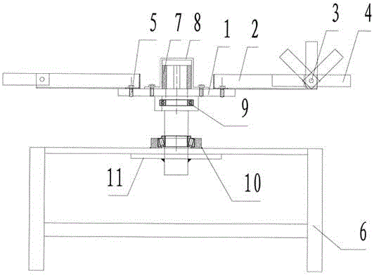
[0009] Embodiments are described in detail in conjunction with the above accompanying drawings, as figure 1 As shown, there is a chassis 11 for installing the rotating shaft at the center of the bracket 6, a rod brace connected to the bracket 6 is welded on the disk surface of the chassis, a shaft hole for assembling the rotating shaft is processed in the center of the disk surface, and one end of the rotating shaft 8 is connected to the rotating platform through the shaft sleeve 7. The central shaft hole assembly on the plate back side, the other end of rotating shaft passes upper bearing seat 9 and lower bearing seat 10 and is seated in the shaft hole installed in chassis 11, seals with cover plate on the central shaft hole of described rotating platform plate 1 front.

[0010] The rotating platform plate is a disc, and the supporting main arm 2 is fixed on the disc surface. The number of the supporting main arms is at least four, which are evenly distributed on the disc. One...


PUM


Abstract

The invention discloses a rotary sandblasting workbench for rotary vibration screen frame and bottom barrel workpieces. A base disc with a rotary shaft is mounted in the center of a support. A pole shore connected with the support is welded to the disc face of the base disc. A shaft hole with the rotary shaft is machined in the center of the disc face. One end of the rotary shaft is assembled to a center shaft hole in the back face of a rotary platform plate through a shaft sleeve. The other end of the rotary shaft penetrates an upper bearing seat and a lower bearing seat and is located and mounted in the base disc shaft hole. A center shaft hole in the front face of the rotary platform plate is sealed with a cover plate. The rotary platform plate is a disc. Supporting main arms are fixedly arranged on the disc face of the disc. One end of each supporting main arm is welded to the edge of the center of the rotary platform plate. The other end of each supporting main arm is connected with an extension arm through a pin shaft. Positioning holes are distributed in the supporting main arms and the extension arms. By the adoption of the technical scheme, the problems that vibrators are not neatly placed and the occupied space is large can be well solved, and the working environment of a workshop can be improved.

Description

technical field [0001] The invention relates to a sandblasting rotary workbench, which is especially suitable for use in sandblasting treatment on the surface of a rotary vibrating screen. Background technique [0002] During the manufacturing process of the rotary vibrating screen, the surface needs to be sandblasted to improve the surface finish and cleanliness of the workpiece, so as to improve the adhesion and corrosion resistance of the covering layer. However, the screen frame and the bottom cylinder of the rotary vibrating screen are circular For the workpiece, it is often necessary to rotate the workpiece to adjust the blasting angle during sandblasting. Due to the heavy weight of the workpiece itself, it is difficult to operate by one person, and often requires the cooperation of 2-3 people, resulting in high labor intensity, low efficiency and long preparation time for the operator. Labor productivity is low. Contents of the invention [0003] The task of the ...

Claims


Application Information

Patent Timeline
IPC IPC(8): B24C1/08B24C3/20
CPCB24C1/08B24C3/20
Inventor 孙志军秦英苏子超卢恩同
Owner XINXIANG ZHEN YING MACHINERY EQUIP CO LTD
Learn More