
Idle stroke transmission gear coupling self-adaption robot finger device
A robot finger and transmission gear technology, which is applied in the direction of manipulators, collets, manufacturing tools, etc., can solve the problems of large deformation of multiple spring parts, difficult selection of spring parts, excessive energy loss, etc., to achieve large grasping force, The effect of stable and reliable gripping, low assembly and maintenance costs
- Summary
- Abstract
- Description
- Claims
- Application Information
AI Technical Summary
Problems solved by technology
Method used
Image

Examples
Embodiment Construction
[0043] The specific structure and working principle of the present invention will be further described in detail below in conjunction with the accompanying drawings and embodiments.
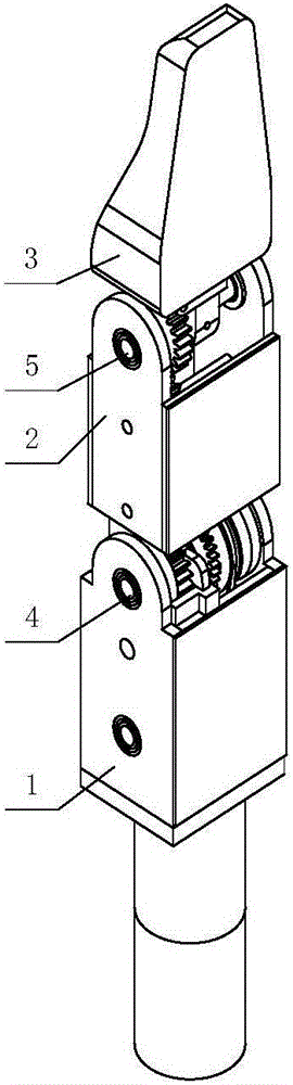
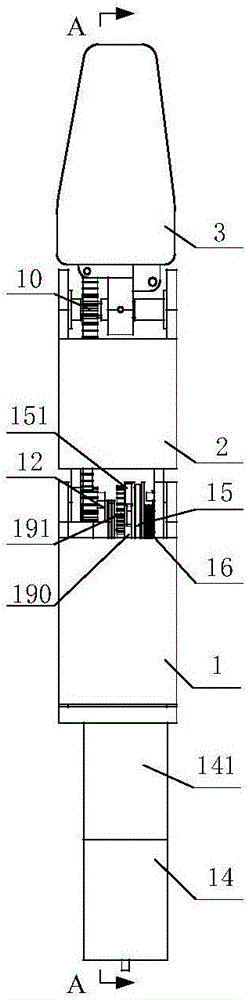
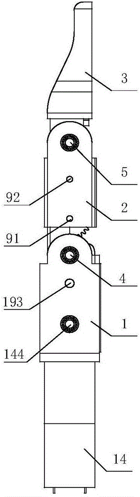
[0044] A kind of embodiment of the free motion transmission gear coupling self-adaptive robot finger device of the present invention design, as Figure 1 to Figure 8 As shown, it includes a base 1, a first finger segment 2, a second finger segment 3, a proximal joint shaft 4, a distal joint shaft 5 and a driver 14; the driver 14 is fixedly connected to the base 1; the proximal joint shaft 4 The centerline of is parallel to the centerline of distal joint axis 5. This embodiment also includes a transition transmission mechanism, a driving dial 152, a first spring member 53, a first gear 9, a second gear 10, a gear set 11, a driven dial 191, an intermediate transmission mechanism, a bump dial 12, The limit protrusion 18 and the second spring 13; the proximal joint shaft 4 is movably sleeved in the ...
PUM
 Abstract
Description
Claims
Application Information