Integrated plastic faucet body forming method

An integrated, plastic technology, applied to household components, household appliances, and other household appliances, can solve problems such as high cost of faucet materials, qualitative changes in glue, and lack of resources, so as to improve production efficiency and quality, prolong service life, The effect is simple to make

Active Publication Date: 2017-02-22
深圳成霖实业有限公司
View PDF7 Cites 7 Cited by
  • Summary
  • Abstract
  • Description
  • Claims
  • Application Information

AI Technical Summary

Problems solved by technology

[0003] At present, there are roughly two production methods for faucet body components on the market. The first production method is to directly adopt the casting production method. The production method is complicated and lengthy, the processing time is long, the efficiency is not high, and the yield is also low. In addition, copper integral casting is used. Although it can meet the requirements of installation strength, due to the lack of resources and the high price of metal, the material cost of the faucet is relatively high, which is not economical and cost-effective.
[0004] The second production method is to make injection molding to make the two side components formed by the valve seat and the foot part on both sides of the faucet component, and the long hollow component at the middle connection part, and then glue them to the opposite parts to form the faucet body. Components; although one-time injection molding can overcome the flow channel in the middle connection part of the molding, it requires a lot of manual bonding and production, and the strength of the bonding part is relatively poor, and the glue is prone to qualitative changes, which seriously affects the quality and service life of the product.

Method used


Image

  • Integrated plastic faucet body forming method
  • Integrated plastic faucet body forming method
  • Integrated plastic faucet body forming method

Examples


Embodiment Construction

[0049] It should be understood that the specific embodiments described here are only used to explain the present invention, not to limit the present invention.

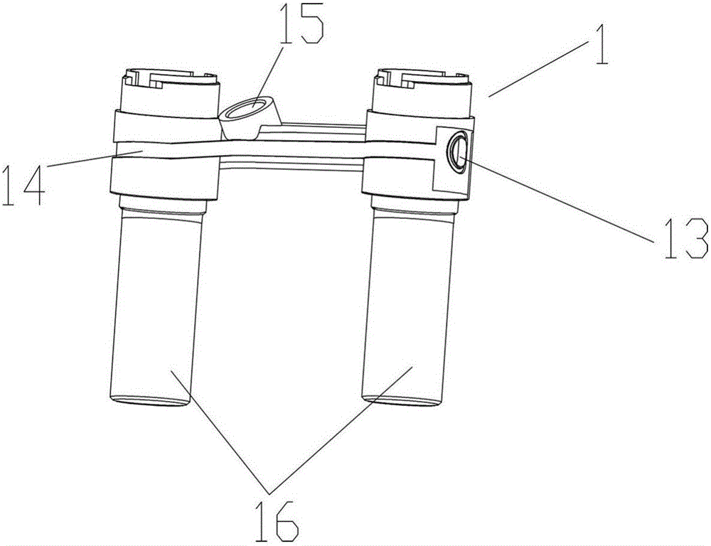
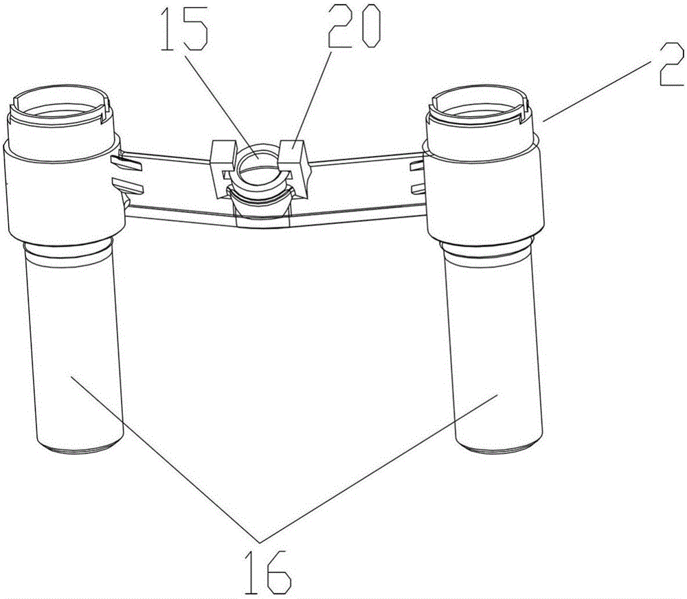
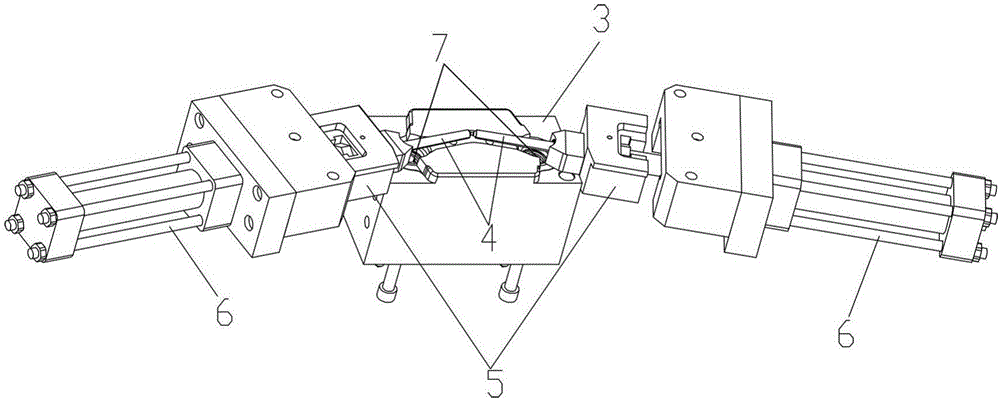
[0050] like Figure 1-8 As shown, a molding die for a one-piece plastic faucet body of the present invention is provided, including a mold base, and a first static mold cavity 24, a second static mold cavity 19 and a first movable mold cavity installed in the mold base. Core 3; after the first static mold cavity 24 is molded with the first movable mold core 3, perform the first injection molding to form the semi-finished product 1 of the integrated plastic faucet body; when the first static mold cavity 24 and the first movable mold After the mold core 3 is molded, the second static mold cavity 19 is molded with the first movable mold core 3, and the second injection molding is performed to form the finished product 2 of the integrated plastic faucet body.

[0051] Wherein, when the semi-finished product 1 is produced...


PUM


Abstract

The invention discloses an integrated plastic faucet body forming mold. The integrated plastic faucet body forming mold comprises a mold frame, a first static mold cavity, a second static mold cavity and a first moving mold core, wherein the first static mold cavity, the second static mold cavity and the first moving mold core are installed in the mold frame; after the first static mold cavity and the first moving mold core are combined, a first injecting molding is conducted, and a semi-finished product of an integrated plastic faucet is formed; and after the first static mold cavity and the first moving mold core is split, the second static mold cavity is combined with the first moving mold core, then a second injection molding is conducted, and a finished product of the integrated plastic faucet is formed. By adopting a manufacturing method of twice injection molding and integrated cladding forming in the finished product, the manufacture method is simple, producing efficiency and the yield of the finished product are high, the effect of fast and mass production is achieved, producing cost is reduced, and a metal connecting pin is added, so that a product is more firm, and the service life is prolonged.

Description

technical field [0001] The invention relates to the technical field of faucet manufacturing, in particular to a molding method for an integrated plastic faucet body. Background technique [0002] In the prior art, most household faucets are faucets with cold and hot water inlet pipes where the water outlets merge together to mix water. The inner core structure of the faucet is composed of two vertical pipes and a horizontal pipe connecting the two vertical pipes. The middle part of the pipe is a mixed water outlet to match the regulating valve. [0003] At present, there are roughly two production methods for faucet body components on the market. The first production method is to directly adopt the casting production method. The production method is complicated and lengthy, the processing time is long, the efficiency is not high, and the yield is also low. In addition, copper integral casting is used. Although it can meet the requirements of installation strength, due to th...

Claims


Application Information

Patent Timeline
Patent Type & Authority Applications(China)
IPC IPC(8): B29C45/06B29C45/14B29C45/33B29L31/00
CPCB29C45/062B29C45/14B29C45/14221B29C45/33B29L2031/7506
Inventor 林士贤
Owner 深圳成霖实业有限公司
Why Eureka
Try Eureka