Composite forming mold with self-provided pressure source and heat source and mold unit

A forming mold with its own pressure technology, which is applied in the field of composite material forming, can solve the problems of low production efficiency, complicated operation and high cost, and achieve the effects of reduced production cost, simple equipment operation and high production efficiency

Inactive Publication Date: 2017-02-22
北京鸿鹄雄狮技术开发有限公司
View PDF8 Cites 0 Cited by
  • Summary
  • Abstract
  • Description
  • Claims
  • Application Information

AI Technical Summary

Problems solved by technology

[0005] The purpose of the present invention is to provide a composite material forming mold and a mold set with its own pressure source and heating source, which are used to solve the problem of complex operation of composite material forming process equipment, low production efficiency, high cost and difficulty in meeting the needs of super large composite materials. The problem of parts forming requirements

Method used


Image

  • Composite forming mold with self-provided pressure source and heat source and mold unit
  • Composite forming mold with self-provided pressure source and heat source and mold unit

Examples


Embodiment 1

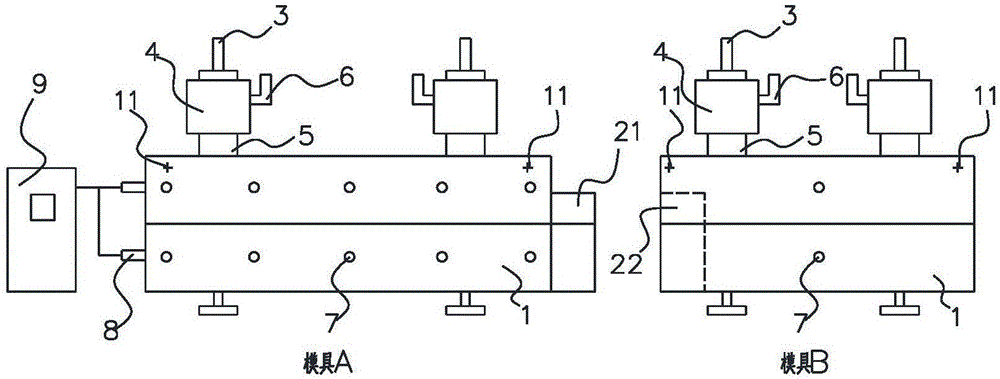
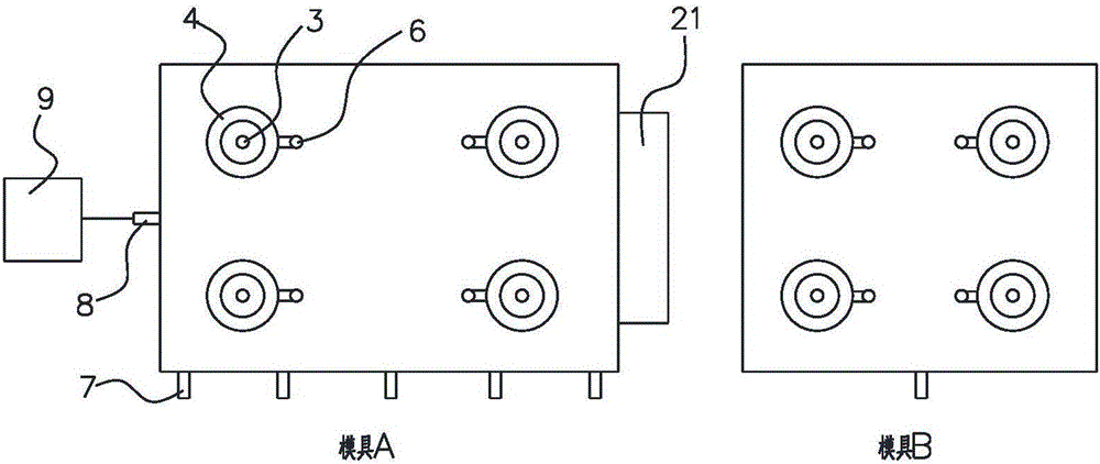
[0023] Such as figure 1 , figure 2 As shown, this embodiment provides a composite material forming mold with its own pressure source and heating source, including mold body 1, pressure source 4, heating source 7 and other components, and pressure source 4 is connected to mold body 1 through force guiding coupling device 3 , the force guiding coupling device 3 runs through the upper and lower surfaces of the mold body 1, and the heating source 7 is connected to the inside of the mold body 1 through the side of the mold body 1 through a thermal pipeline, wherein the pressure source 4 can be an air pressure source or a hydraulic source or a mechanical Pressure source, heating source 7 can choose oil bath source or electric heating source. The pressure source 4 pressurizes the mold body 1 through the force-guiding coupling device 3 to exert pressure on the laminated composite material in the mold body 1 . In this embodiment, there can be multiple pressure sources 4, and multipl...

Embodiment 2

[0026] Such as figure 1 , figure 2 As shown, the present invention also provides a composite material molding die set with its own pressure source and heating source, including a plurality of composite material molding dies with its own pressure source and heating source in Example 1, and the sides of the mold body 1 One side is provided with a locking groove 22 , and the other side of the side of the mold body 1 is provided with a locking block 21 engaged with the locking groove 22 . A plurality of composite molding molds with their own pressure sources and heating sources are combined into a large mold through the slot 22 and the block 21 to meet the molding requirements of various composite material parts, especially for super large composite materials. Forming requirements of parts. It should be noted that the mold cavities of mold A, mold B, mold C... (only mold A and mold B are shown in the figure) are interconnected, and can be sealed through the lap groove 22 and bl...


PUM


Abstract

The invention discloses a composite forming mold with a self-provided pressure source and heat source, and a mold unit. The composite forming mold with the self-provided pressure source and heat source comprises a mold body, the pressure source and the heat source, and the pressure source is connected with the mold body by a conductive connection device. The conductive connection device penetrates the upper and lower surfaces of the mold body, and the heat source is connected with the mold body through the heat pipe. The composite forming mold has the advantages that the independent pressing equipment and the heating equipment are no longer needed, the operation of the equipment is simple, the production efficiency is high and the production cost is significantly reduced; the molding demand of the composite parts of different sizes can be satisfied, and particularly the molding needs of ultra-large composite parts can be met.

Description

technical field [0001] The invention relates to the technical field of composite material forming, in particular to a composite material forming mold and a mold set with its own pressure source and heating source. Background technique [0002] Composite molding process usually requires the parts to be cured and formed under specified temperature and pressure to realize the parts. Usually use a hot press to heat up and pressurize to form a mold, or use an autoclave to heat up and pressurize to form a mold, or use a curing furnace to heat up and absorb it with a heat shrinkable belt, vacuum pump, resin liquid injection, etc. to provide pressure to form a mold. At present, the molding process of composite materials requires molding equipment such as hot presses, autoclaves, and curing furnaces. The operation of the equipment is complex, the overall production efficiency is low, and the cost is high. It is difficult to meet the molding needs of super-large composite parts. [0...

Claims


Application Information

Patent Timeline
Patent Type & Authority Applications(China)
IPC IPC(8): B29C70/54B29C33/02B29C33/20B29C33/30
CPCB29C70/54B29C33/02B29C33/20B29C33/302
Inventor 冯跃飞
Owner 北京鸿鹄雄狮技术开发有限公司
Why Eureka
Try Eureka