Dual-purpose fin stabilizer used at zero speed and certain speed

A fin stabilization and speed technology, applied in the field of fin stabilization, can solve the problem of insufficient stabilization effect, etc., and achieve the effects of improved brief effect, high stabilization efficiency and simple structure

Inactive Publication Date: 2017-02-22
HARBIN ENG UNIV
View PDF6 Cites 5 Cited by
  • Summary
  • Abstract
  • Description
  • Claims
  • Application Information

AI Technical Summary

Problems solved by technology

[0004] The purpose of the present invention is to provide a dual-purpose fin stabilizer with zero speed and

Method used


Image

  • Dual-purpose fin stabilizer used at zero speed and certain speed
  • Dual-purpose fin stabilizer used at zero speed and certain speed
  • Dual-purpose fin stabilizer used at zero speed and certain speed

Examples


Embodiment Construction

[0011] The present invention will be described in further detail below with reference to the accompanying drawings and specific embodiments.

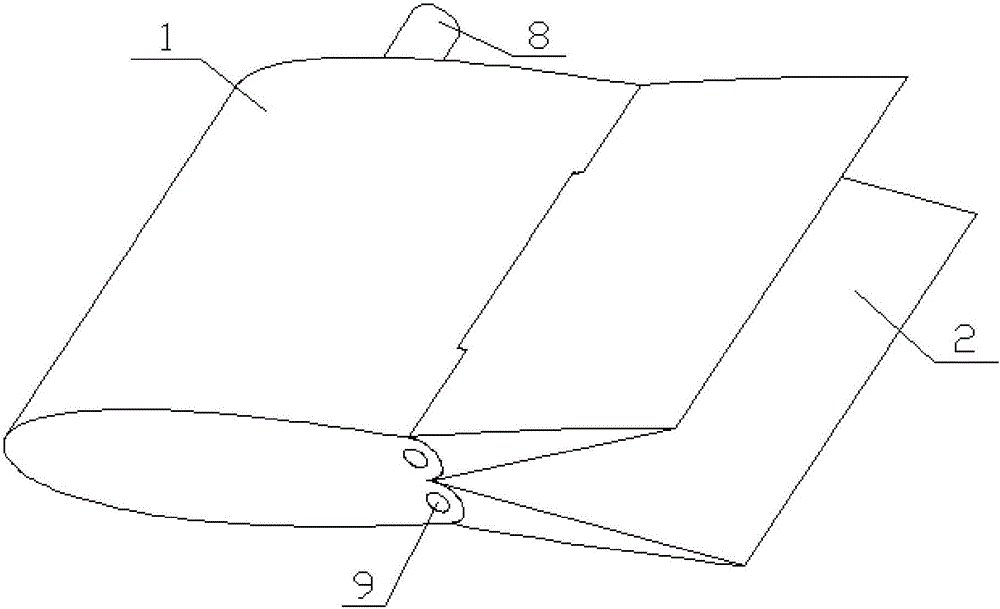
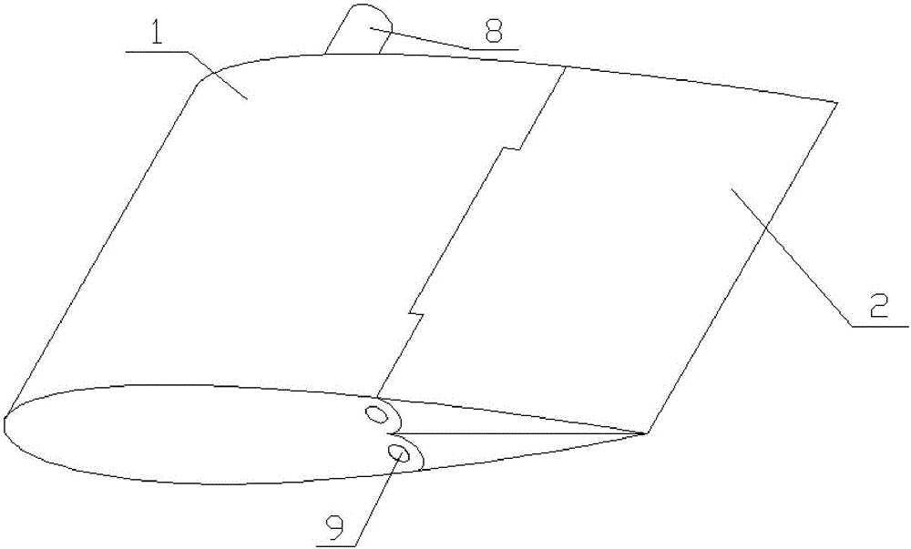
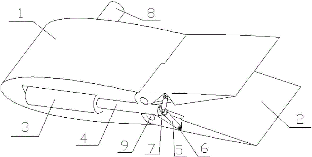
[0012] The present invention is mainly composed of a main wing 1, a flap 2 and a hydraulic cylinder 3; wherein, the main wing 1 and the flap 2 are hinged through a connecting shaft 9; the flap is divided into two symmetrical halves, which are respectively hinged to the main wing; Inside, the end of the hydraulic rod 4 is hinged with the connecting rod 5; one end of the connecting rod 5 is hinged with the hydraulic rod through the pin B7, and the other end is hinged with the flap through the pin A6; the large rotating shaft 8 is fixedly connected with the main wing 1. During anti-sway operation, the whole device is driven to swing up and down by the large rotating shaft 8 to generate lift and realize anti-sway. When there is a speed, the hydraulic cylinder is controlled by the control program to retract the hydraulic rod and drive the fl...


PUM


Abstract

The invention provides a dual-purpose fin stabilizer used at a zero speed and a certain speed. The dual-purpose fin stabilizer mainly consists of a main wing, a wing flap and a hydraulic cylinder, wherein the main wing is hinged to the wing flap through a rotating shaft; the wing flap is divided into two symmetrical parts, and the two parts are respectively hinged to the main wing; the hydraulic cylinder is fixed in the main wing; the end part of a hydraulic rod is hinged to a connecting rod; one end of the connecting rod is hinged to the hydraulic rod, and the other end of the connecting rod is hinged to the wing flap; a large rotating shaft is fixedly connected with the main wing; when the fin stabilizer works, the large rotating shaft drives the whole device to swing up and down to generate lifting force, so that stabilizing is realized; at a certain speed, the hydraulic cylinder is controlled by a control program to retract the hydraulic rod, and the wing flap is driven to close to reduce resistance; and at a zero speed, the hydraulic rod extends to enable the wing flap to be opened, so that the lifting force is enlarged. The dual-purpose fin stabilizer disclosed by the invention can work when a vessel is at a certain speed and at a zero speed, and is simple in structure, high in stabilizing efficiency, and low in flow noise; and the dual-purpose fin stabilizer is symmetrically arranged on two sides of the vessel (figures are respectively starboard), and is suitable for all kinds of vessels.

Description

technical field [0001] The invention relates to a fin stabilizer, in particular to a dual-purpose fin stabilizer with zero speed and with speed, belonging to the field of ships and marine engineering. Background technique [0002] Ships will inevitably produce various swaying in wind and waves, namely roll, pitch, yaw, sway, surge and heave, among which roll is the most significant and has the greatest impact. The severe rolling motion seriously affects the ship's seaworthiness, equipment safety and crew comfort. Therefore, it is very important to improve the rolling stability. Fin stabilizer is currently the most commonly used and most successful ship anti-rolling device. However, the current fin stabilizers are more effective for ships at medium and high speeds, but when the ships are at low or even zero speeds, because the speed relative to the water is relatively small, the lift generated is also more effective, and the brief effect is relatively limited. [0003] In r...

Claims


Application Information

Patent Timeline
IPC IPC(8): B63B39/06
CPCB63B39/06
Inventor 王庆熊大鹏丁勇胡开业
Owner HARBIN ENG UNIV
Why Eureka
Try Eureka