Single main beam member of hoisting equipment

A technology of lifting equipment and single main girder, which is applied in the direction of supporting structure, load hanging components, track system, etc., can solve the problems of hidden safety hazards, increased weight, and large manual labor, so as to achieve the convenience of outer seam welding and not easy Effect of fatigue deformation and enhanced stability

Inactive Publication Date: 2010-05-12
李登平
View PDF6 Cites 0 Cited by
  • Summary
  • Abstract
  • Description
  • Claims
  • Application Information

AI Technical Summary

Problems solved by technology

[0011] 2. It is difficult to install and weld the side panels on both sides of the car body beam
Due to the use of multi-section tailor welding and sub-section and block installation, temporary fixture crowbar welding is also required, and finally large weld seam welding, flame correction, etc., the entire process requires a lot of labor, labor and materials can not guarantee product quality
[0012] 3. The I-beam is used as the track, and the upper edge plate of the I-beam is only wrapped in the car body, which not only causes material waste, but also increases the weight unnecessarily. The lower edge plate is used as the track because the tread is not wide enough, and the electric hoist Unilateral drive, shaking on both sides during operation, on the one hand forms resistance, on the other hand affects the service life of the hoist machinery
[0013] 4. When the span exceeds the standard, the "single main girder" has a large rebound rate for the up and down jog of the hanging load, and the sideways shaking of the jog movement of the cart is obvious, the performance is very unstable, and there are potential safety hazards

Method used


Image

  • Single main beam member of hoisting equipment
  • Single main beam member of hoisting equipment
  • Single main beam member of hoisting equipment

Examples


Embodiment Construction

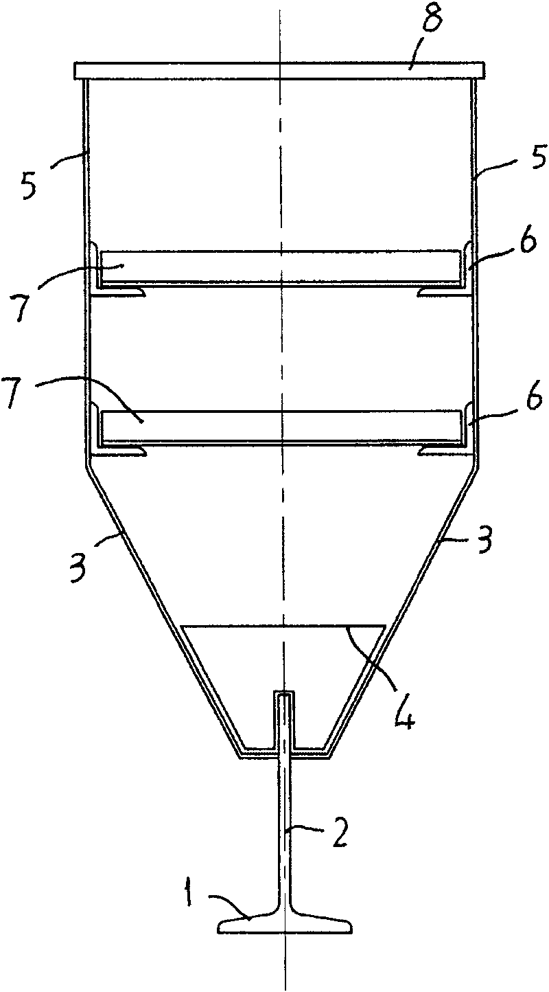
[0033] see figure 1 , figure 2 , The present embodiment is made of track and box body.

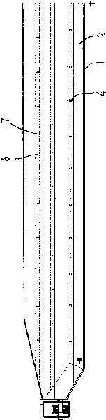
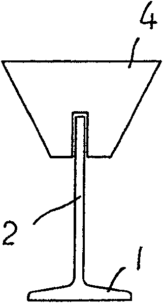
[0034] figure 1 As shown, the track adopts an inverted "T"-shaped cross-section structure, with its lower horizontal track tread 1 and its upright plate as the longitudinal main rib 2 of the track, and the top of the main rib 2 is connected to the two side plates arranged in a "V" shape 3, between the bottom of the "V" shaped side plate 3 and the main rib 2, a track positioning reinforced version 4 ( image 3 shown), and at the top of the "V" shaped side panel, the bending part is raised upwards to connect the upright wall panels 5 on both sides to form a box body.

[0035] figure 1 , figure 2 As shown, on the inner side walls of the wall panels 5 on both sides, a longitudinal process angle iron 6 is arranged along the track direction, and a horizontal horizontal support rib 7 is arranged between the longitudinal process angle irons 6 on both sides. Connect the widened and thickene...


PUM


Abstract

The single main beam member for hoisting equipment consists of tracks and carriage, and features the tracks in turned T-structure with lower transverse plane as the tread, vertical plate as the main longitudinal reinforcing bar, V-shaped side plates on the main reinforcing bar and vertical track reinforcing bar between the V-shaped side plates and the main reinforcing bar; and the carriage formedwith the vertical wall plates connected to the top of the V-shaped side plates and the top cover. The present invention is used in production line and has ensured track linearity, camber and tread levelness, increased track tread and main reinforcing bar width and thickness to ensure the running stability of the electric hoist and other advantages.

Description

technical field [0001] The invention relates to a special equipment component, more specifically a single main girder component of heavy equipment. technical background [0002] Electric hoist single-girder bridge cranes, electric hoist suspension cranes, electric hoist gantry cranes, electric hoist semi-gantry cranes are referred to as electric hoist bridges, and gantry cranes all use "single main girder" as the main structure. [0003] Among them, single-girder bridge cranes and suspension cranes use "single main girder" as the main structure, and are equipped with end girders at both ends, mechanical transmission structures and electrical systems to form complete sets of equipment. Electric hoist gantry and semi-gantry cranes use "single main girder" as the main structure to prepare gantry outriggers, upper and lower end beams, mechanical transmission mechanisms and electrical systems as complete sets of equipment. [0004] Electric hoist bridge gantry cranes are widely ...

Claims


Application Information

Patent Timeline
IPC IPC(8): B66C7/02B66C6/00
Inventor 李登平
Owner 李登平
Why Eureka
Try Eureka