
Circuit board automatic loading device

An automatic loading and circuit board technology, applied in packaging, loading/unloading, transportation and packaging, etc., can solve problems such as poor storage uniformity of circuit boards, shaking and shifting of substrate boxes, and uneven contact between circuit boards and pushing mechanisms. , to achieve the effect of improving storage uniformity and improving work efficiency

Inactive Publication Date: 2017-02-22
TIANJIN MINNING ELECTRONICS
View PDF0 Cites 13 Cited by
  • Summary
  • Abstract
  • Description
  • Claims
  • Application Information

AI Technical Summary

Problems solved by technology

[0003] 1. The circuit board on the conveyor belt is transported to the push mechanism, and the circuit board is easy to slip in the push mechanism, which makes the contact between the circuit board and the push mechanism unstable, which causes the push mechanism to push the circuit board to the slot of the substrate box. Makes the storage order of the circuit board poor
[0004] 2. The lifting mechanism drives the substrate box to continuously move up and down, and the pushing mechanism also continuously pushes the circuit board into the slot of the substrate box. Moving the substrate box up and down and inserting the circuit board into the substrate box is prone to shaking and shifting of the substrate box, making Substrate box is less stable

Method used


Image

  • Circuit board automatic loading device

Examples


Embodiment Construction

[0025] The present invention will be described in detail below in conjunction with the accompanying drawings.

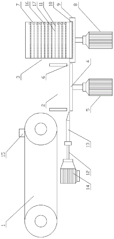
[0026] like figure 1 As shown in the structural diagram of the present invention, the present invention provides an automatic circuit board loading device, which includes a conveyor 1, a transfer device 2 and a storage device 3 arranged in sequence, and the transfer device 2 includes a transfer box 4 and is arranged on The first lifting motor 5 at the bottom of the dump box, the top of the dump box 4 is an open structure, and the bottom of the dump box 4 is provided with an output port 6 for a single circuit board to pass through, and at the bottom of the dump box 4 A pushing device 12 that pushes the circuit board out from the output port 6 is also installed. The storage device 3 includes a storage box 7 and a second lifting motor 8. The top of the driving rod of the second lifting motor 8 is fixedly connected with an operating table 9. A groove 10 is provided on t...


PUM


Abstract

The invention provides a circuit board automatic loading device. The circuit board automatic loading device includes a conveying machine, an unloading device and a storage device; the unloading device includes an unloading box and a first lifting motor arranged under the unloading box; the top of the unloading box is opened; an output opening for allowing a single circuit board to pass through is formed in the bottom of the unloading box; a pushing device for pushing the circuit board out of the output opening is arranged on the bottom of the unloading box; the storage device includes a storage box and a second lifting motor; a drive rod of the second lifting motor is fixedly connected to an operation table; a groove is formed in the operation table; the storage box is arranged in the groove; partition plates for holding the circuit boards are horizontally arranged in the storage box; and the partition plates are in butt joint with the output opening. The beneficial effects of the invention are that the uniformity and the stability of circuit board automatic loading is good.

Description

technical field [0001] The invention belongs to the technical field of circuit board loading equipment, in particular to an automatic circuit board loading device. Background technique [0002] At present, as the upgrading of electronic products continues to accelerate, the task load of the circuit board production line is also increasing. However, efficient and fast production of circuit boards is an urgent need for the production line. The production line conveys circuit boards through conveyor belts. It is necessary to remove the circuit board from the conveyor belt during the position, but manually remove it from the conveyor belt and place it in the storage box, which not only increases the labor intensity, but also is difficult to improve the production efficiency. The automatic circuit board loading device in the prior art mainly includes the substrate box , slots, pushing mechanism, lifting mechanism and unloading platform, the circuit board on the conveyor belt ente...

Claims


Application Information

Patent Timeline
IPC IPC(8): B65B5/10B65B35/20B65B35/56B65G47/24B65G47/82B65G65/02
CPCB65B5/10B65B35/205B65B35/56B65G47/24B65G47/82B65G65/02
Inventor 胡志有
Owner TIANJIN MINNING ELECTRONICS
Learn More