Speed reducer storing device

A storage device and reducer technology, which is applied in the directions of packaging food, assembly machines, assembly vehicles, etc., can solve problems such as aging, affecting performance, corrosion of reducer, etc., to achieve convenient handling and batch transfer, and avoid direct contact with air , the effect of prolonging the storage time

Inactive Publication Date: 2017-02-22
常州耐强传动机械有限公司
View PDF5 Cites 0 Cited by
  • Summary
  • Abstract
  • Description
  • Claims
  • Application Information

AI Technical Summary

Problems solved by technology

The traditional storage is only to place the reducer directly in the warehouse. Short-term storage will not be affected. If it is stored for

Method used


Image

  • Speed reducer storing device
  • Speed reducer storing device
  • Speed reducer storing device

Examples


Embodiment Construction

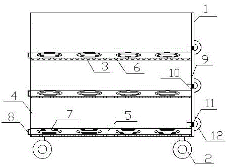
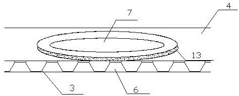
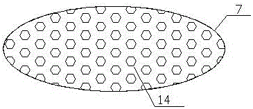
[0017] Such as figure 1 It is a structural schematic diagram of the present invention, figure 2 is a partially enlarged schematic diagram of the base plate, image 3 is the schematic diagram of the bottom of the base plate, Figure 4 It is the right view of the box body, a storage device for a reducer, including a box body 1, a pulley 2 is provided at the bottom of the box body 1, and several fixing plates 3 are arranged inside the box body 1, and the fixing plates 3 are horizontally fixed on the Inside the box body 1, and the box body 1 is divided into several compartments 4, a base layer 5 is arranged above the fixed plate 3, a roller bar 6 is arranged on the surface of the fixed plate 3, the base layer 5 is placed on the roller bar 6, and the base layer 5 is provided with a circular hole 15 on the surface, and a base plate 7 is placed in the circular hole 15. One end of the base layer 5 is provided with a pull ring 8, and the pull ring 8 is arranged on the outside of the...


PUM

PropertyMeasurementUnit
Heightaaaaaaaaaa
Diameteraaaaaaaaaa

Abstract

The invention relates to the technical field of speed reducers, in particular to a speed reducer storing device which comprises a box. Pulleys are arranged on the bottom of the box. A plurality of fixing plates are arranged in the box. Fixing plates are horizontally fixed into the box in a welded manner and divide the box into a plurality of compartments. A base layer is arranged on each fixing plate. The surface of each fixing plate is provided with an idler wheel strip. Each base layer is arranged on the corresponding idler wheel strip. The surface of each base layer is provided with round holes. A base disc is arranged in each round hole. A pull ring is arranged at one end of each base layer. The pull rings are arranged on the outer side of the box. The other ends of the pull rings are fixed to the inner side of the box through fixing devices. The speed reducer storing device can store speed reducers in a separated manner, the situation that the speed reducers make direct contact with air is avoided, storage time of the speed reducers is prolonged, and moreover, the device also facilitates taking and batch transferring of the speed reducers and is convenient speed reducer storing equipment suitable for actual production.

Description

technical field [0001] The invention relates to the technical field of reducers, in particular to a storage device for a reducer. Background technique [0002] As the reducer is widely used in modern machinery, the output of the reducer is also increasing year by year. A large number of production causes some reducers to stay in the warehouse. Therefore, the reasonable storage of the reducer has become a major problem for manufacturers. The traditional storage is only to place the reducer directly in the warehouse. Short-term storage will not be affected. If it is stored for a long time, the moisture in the air will corrode the reducer, resulting in rust and aging of the reducer, which will affect the performance. Contents of the invention [0003] In order to overcome the existing deficiencies, the invention provides a storage device for a reducer. [0004] The technical solution adopted by the present invention to solve the technical problem is: a storage device for a r...

Claims


Application Information

Patent Timeline
IPC IPC(8): B65D25/02B65D25/24B65D85/68
CPCB65D25/02B65D25/24B65D85/68
Inventor 周晓峰
Owner 常州耐强传动机械有限公司
Why Eureka
Try Eureka