
a security machine

A technology of security inspection machine and linkage mechanism, which is applied in the direction of conveyors, instruments, nuclear radiation exploration, etc., and can solve the problems of increasing use cost, affecting use, and reducing the use efficiency of security inspection machines.

Active Publication Date: 2018-11-06
NUCTECH CO LTD
View PDF12 Cites 0 Cited by
  • Summary
  • Abstract
  • Description
  • Claims
  • Application Information

AI Technical Summary

Problems solved by technology

[0005] Whether it is a vehicle-mounted security inspection machine or a foldable security inspection machine, if the security inspection machine is placed with the conveyor belt in the retracted position for a long time, the shielding curtain will be deformed when it is bent, and the deformed shielding curtain cannot be completely blocked when in use. The rays scattered outward in the channel of the security inspection machine form a safety hazard; once the deformation of the shielding curtain affects the use, it needs to be replaced, which reduces the efficiency of the security inspection machine and increases the cost of use
[0006] At the same time, in order to enable the conveyor belt to smoothly flip from the working position to the retracted position, the existing structure usually lengthens the shielding curtain, resulting in the length of the shielding curtain being greater than the height of the passage in the security inspection machine
The user generally judges the height of the channel in the security inspection machine based on the length of the shielding curtain. That is to say, the user generally regards the length of the shielding curtain as the passable height. Bring misleading, affect the use

Method used


Image

  • a security machine
  • a security machine
  • a security machine

Examples


Embodiment 1

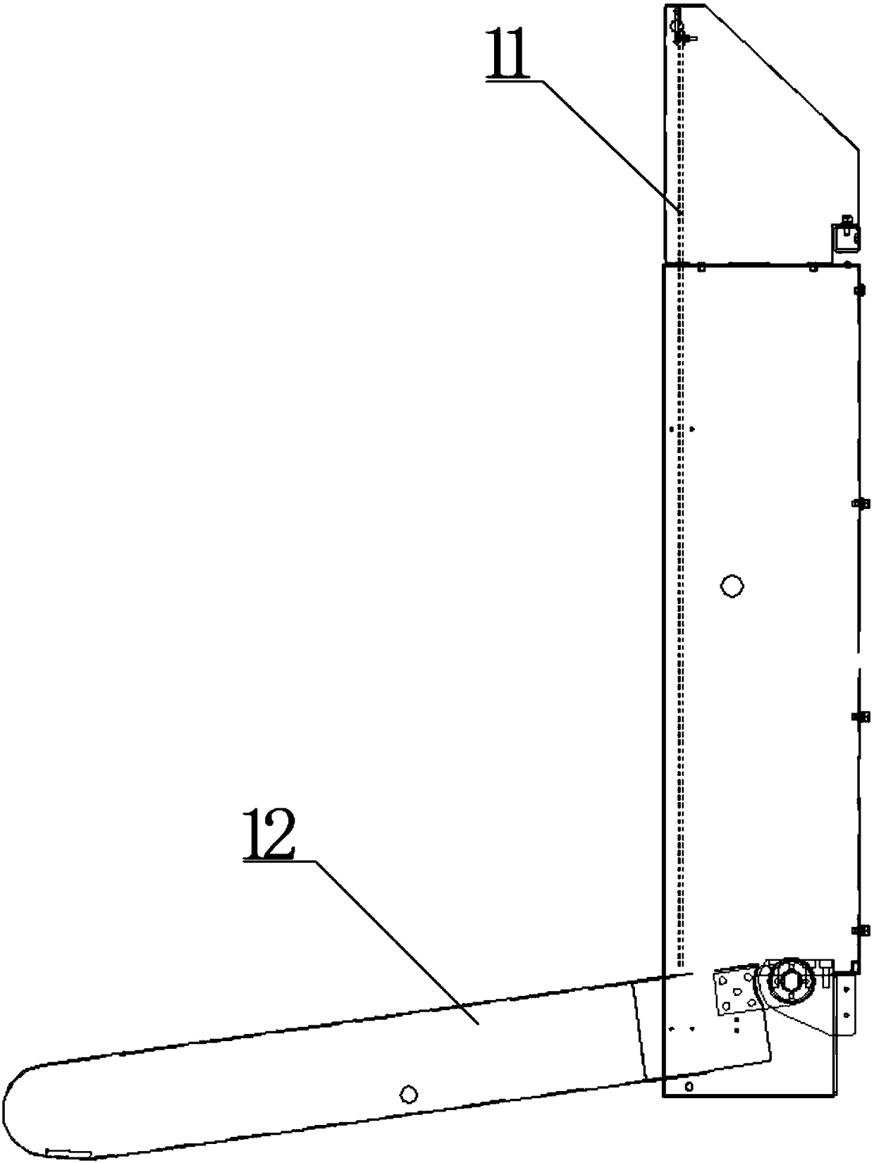
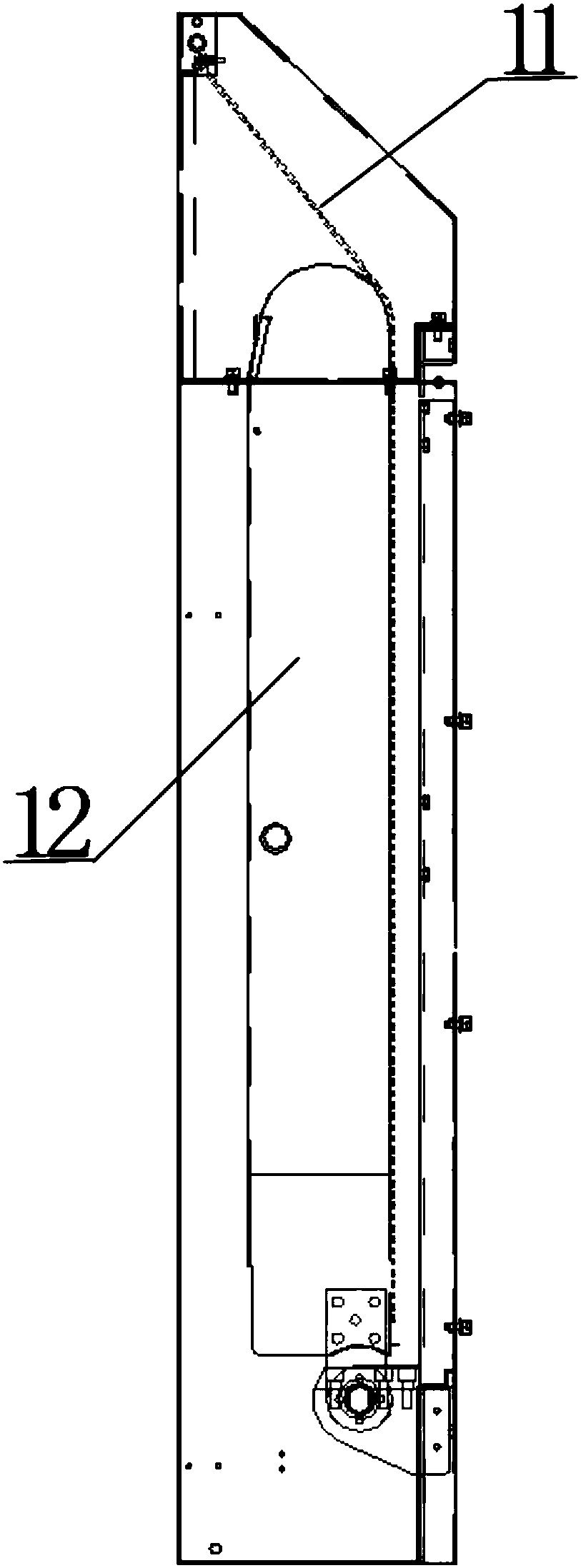
[0040] refer to figure 1 with figure 2 The current security inspection machine includes a shielding curtain 11 and a conveyor belt 12. The conveyor belt 12 can rotate between a working position that plays a role in transmission and a retracted position that is stored in the channel of the security inspection machine. The shielding curtain 11 is clamped and fixed by a steel plate and then hung on the Above the entrance of the security inspection machine. Wherein, it can be understood that the security inspection machine channel includes two channel openings, which are respectively used as the entrance and the exit of the security inspection machine channel. leakage.

[0041]Taking the vehicle-mounted security inspection machine as an example, the conveyor belt 12 is in the working position when it is parked and used. At this time, the shielding curtain 11 naturally droops under its own gravity and is in a vertical state, covering the channel opening of the security inspectio...


PUM


Abstract

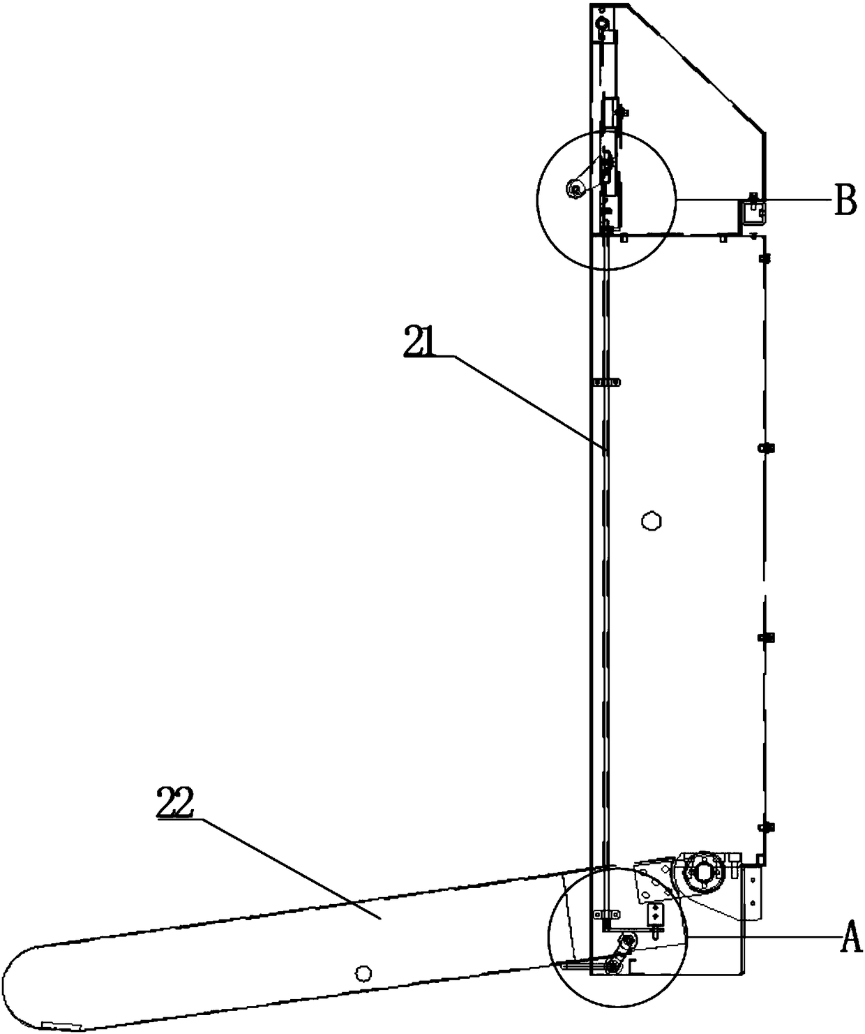
The invention relates to the technical field of security inspection, in particular to a security inspection machine. The security inspection machine comprises a baffle capable of rotating between a vertical position and an inclination position. A shielding curtain is connected to the baffle vertically as a whole when the baffle is located in the vertical position and the inclination position. A conveying belt pushes the baffle to rotate from the vertical position to the inclination position when rotating from a work position to a put-away position. The shielding curtain is spaced to the conveying belt all the time in the rotation process of the baffle. Thus, the shielding curtain is always kept vertical and cannot be pushed by the put-away conveying belt to be bent, the shielding curtain cannot be deformed when the conveying belt is put away no matter how long the security inspection machine is placed, safety hidden hazards do not exist, use efficiency of the security inspection machine is improved, and use cost is reduced. Besides, the length of the shielding curtain can be arranged to be equal to the height of an internal channel of the security inspection machine, a user can accurately judge the height of the internal channel of the security inspection machine according to the length of the shielding curtain, and the security inspection machine is convenient to use.

Description

technical field [0001] The invention relates to the technical field of security inspection, in particular to a security inspection machine. Background technique [0002] The current security inspection machine includes a conveyor belt and a shielding curtain. In a vehicle-mounted security inspection machine or a foldable security inspection machine, the conveyor belt can rotate between the working position for transmission and the stowed position stored in the channel of the security inspection machine. The curtain is clamped and fixed with steel plates and then hung at the channel opening of the security inspection machine channel. [0003] Taking the vehicle-mounted security inspection machine as an example, the conveyor belt is in the working position when it is parked and used. At this time, the shielding curtain naturally droops under its own gravity and is in a vertical state to block the channel opening of the security inspection machine channel and is used to block t...

Claims


Application Information

Patent Timeline
Patent Type & Authority Patents(China)
IPC IPC(8): B65G21/12G01V5/00
CPCB65G21/12G01V5/00
Inventor 李喜猛王勤忏杨中荣张金宇
Owner NUCTECH CO LTD
Learn More