RH method vacuum tank with lifting gas pipeline and arrangement method of lifting gas pipeline thereof

A gas pipeline and arrangement method technology, applied in the field of RH method refining equipment, can solve the problems affecting the life of the lower groove of the vacuum tank, fast erosion rate, increase the cost of refractory materials, etc., to improve the life of refractory materials, reduce erosion erosion, reduce Effect of refractory cost

Inactive Publication Date: 2017-02-22
MCC CAPITAL ENGINEERING & RESEARCH
View PDF4 Cites 0 Cited by
  • Summary
  • Abstract
  • Description
  • Claims
  • Application Information

AI Technical Summary

Problems solved by technology

[0004] The circulation of molten steel is fixed in the vacuum tank and flows from the riser to the downcomer. Since the molten steel has a certain flow rate, it will cause a large erosion of the vacuum tank refractory material on the downcomer side, making the vacuum tank refractory material on the downcomer side due to erosion. Erosion The erosion rate is fast, and the refractory material must be replaced offline after a certain number of furnaces are used, which affects the life of the lower tank of the vacuum tank, thereby increasing the cost of the refractory material

Method used


Image

  • RH method vacuum tank with lifting gas pipeline and arrangement method of lifting gas pipeline thereof

Examples


Embodiment Construction

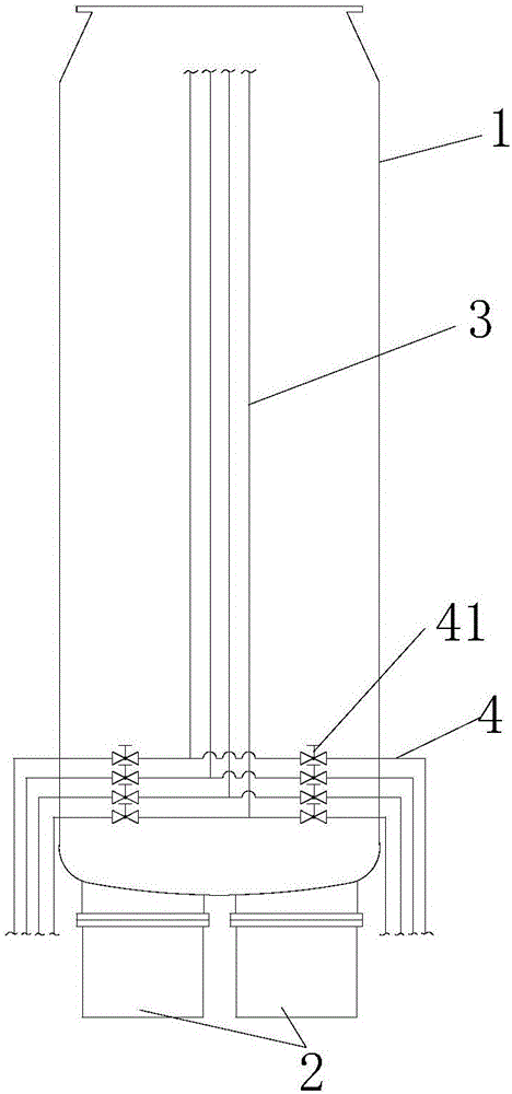
[0025] The present invention proposes a RH method vacuum tank with a lifting gas pipeline, comprising: a vacuum tank, the vacuum tank is vertically placed, and two dipping tubes are inserted at the bottom thereof, and the two dipping tubes are parallel to each other, and are respectively connected to The inner cavity of the vacuum tank is connected; at least one lifting pipeline is vertically arranged on the outside of the vacuum tank, and its lower end is connected with two branch pipelines, and a valve is respectively installed on the two branch pipelines. The free ends correspond to communicate with the two dipping pipes.

[0026] The present invention also proposes a method for arranging the lifting gas pipeline of the RH method vacuum tank, which includes the following steps: S1: Install two dipping tubes at the bottom of the vacuum tank placed vertically, and make the dipping tubes and the The inner cavity of the vacuum tank is connected; S2: At least one lifting pipelin...


PUM


Abstract

The invention proposes a RH method vacuum tank with a lifting gas pipeline and an arrangement method of the lifting gas pipeline thereof. The RH method vacuum tank comprises a vacuum tank and at least one lifting pipeline, wherein the vacuum tank is vertically placed, and the bottom thereof is inserted with two dipping pipes; the two dipping pipes are parallel to each other, and are respectively communicated with an inner cavity of the vacuum tank; the lifting pipeline is vertically arranged on the outer side of the vacuum tank, and the lower end thereof is communicated with two branch pipelines; valves are respectively mounted on the two branch pipelines; and free ends of the two are correspondingly communicated with the two dipping pipes. The arrangement method comprises the following steps: (S1) two dipping pipes are mounted at the bottom of the vacuum tank vertically placed, and are communicated with the inner cavity of the vacuum tank; (S2) at least one lifting pipeline is vertically arranged on the outer side of the vacuum tank; the lower end of the lifting pipeline is communicated with two branch pipelines; and the valves are respectively mounted on the two branch pipelines; and (S3) the free ends of the two branch pipelines are correspondingly communicated with the two dipping pipes. The RH method vacuum tank can prolong the material resisting life of the lower part thereof.

Description

technical field [0001] The invention relates to the technical field of RH method refining equipment, in particular to an RH method vacuum tank with a lifting gas pipeline and a method for arranging the lifting gas pipeline. Background technique [0002] The RH method (RH-vacuum degassing), that is, the vacuum cycle degassing method, was jointly developed by the former Ruhrstahl and Heraeus in 1957, so it became the RH method, and the vacuum treatment is An important way of refining outside the furnace plays a very important role in providing steel product quality, expanding quality, reducing costs, and optimizing steelmaking production processes. It is an indispensable production equipment for automotive sheets, electrical steel, pipeline steel, etc. . [0003] When the RH method is used to treat molten steel, the ladle is first sent to the processing position with a ladle car, and the ladle is lifted to make the dipping tube dip a certain distance below the liquid steel su...

Claims


Application Information

Patent Timeline
Patent Type & Authority Applications(China)
IPC IPC(8): C21C7/10
CPCC21C7/10
Inventor 杜善国李博
Owner MCC CAPITAL ENGINEERING & RESEARCH
Why Eureka
Try Eureka