Side burning device structure of float glass smelting kiln

A technology of float glass and device structure, which is applied in the field of structural devices to realize side-firing production of float glass melting furnaces, and can solve problems such as small contact area between combustion-supporting air and fuel, uneven and effective mixing, erosion of small furnace side walls, etc. problems, to achieve the effect of shortening the black area, increasing the effective heat transfer area, and reducing erosion and erosion

Active Publication Date: 2012-05-23
长利玻璃洪湖有限公司
View PDF0 Cites 0 Cited by
  • Summary
  • Abstract
  • Description
  • Claims
  • Application Information

AI Technical Summary

Problems solved by technology

The existence of the black area reduces the coverage area of ​​the flame in the furnace and reduces the heat transfer effect
In addition, the contact area between combustion-supporting air and fuel is relatively small during bottom combustion, and it is difficult to achieve uniform mixing, which reduces fuel efficiency; especially for gas and natural gas fuels with relatively slow combustion speeds, the fuel cannot be mixed evenly and effectively, and the fuel is incompletely burned. Cause waste, not conducive to energy-saving and efficient production
However, the arc burners used in the existing side burners are all straight burners. After the straight burners are arranged on the side wall, the jet flames on both sides will interfere with each other, and the flame will interfere with the small furnace. Scouring erosion of side walls

Method used


Image

  • Side burning device structure of float glass smelting kiln
  • Side burning device structure of float glass smelting kiln
  • Side burning device structure of float glass smelting kiln

Examples


Embodiment Construction

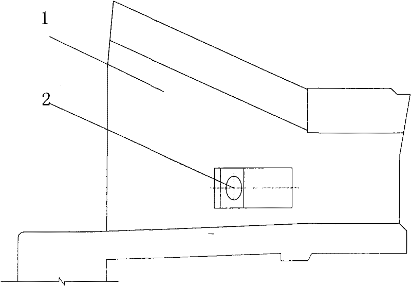
[0022] like figure 1 As shown, it is a side wall 1 of a small furnace, and the lower part of the side wall 1 is provided with a burner guide hole 2 .

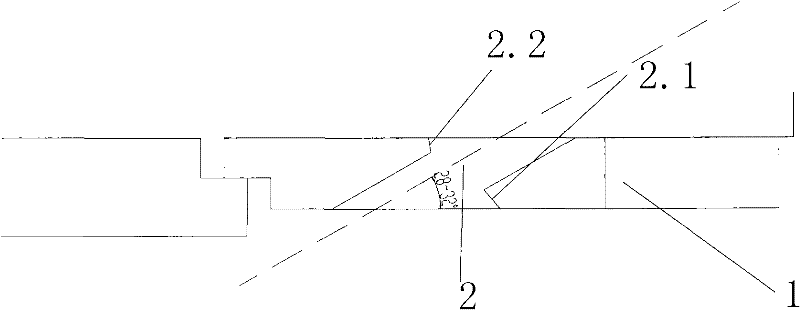
[0023] The structure of the burner guide hole 2 is as follows figure 2 As shown, the burner guide hole and the axis of the side wall are arranged obliquely, and the angle between the center line of the burner guide hole and the axis of the side wall is 25° to 35°, and the optimum angle is 28° to 32°. A first limit plane 2.1 is set on the outer side of the side wall in one end of the burner guide hole 2, and a second limit plane 2.2 is set on the inner side of the side wall in the other end of the burner guide hole 2. The first limit plane 2.1 and the second limit plane 2.1 Plane 2.2 is relatively misaligned. The first limit plane 2.1 and the second limit plane 2.2 are arranged in a relative dislocation, which can ensure that the side-burning brick 3 is inserted between the two limit planes.

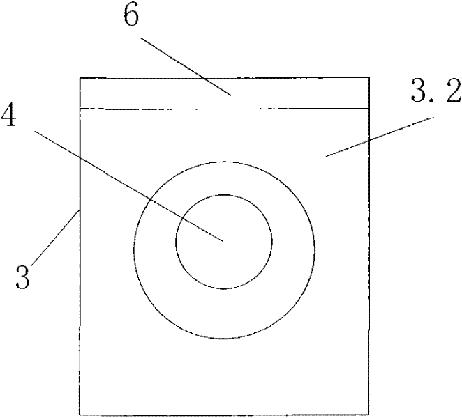
[0024] The structure of side bu...


PUM

PropertyMeasurementUnit
angleaaaaaaaaaa

Abstract

The invention discloses a side burning device structure of a float glass smelting kiln, comprising a side wall of the float glass smelting kiln, a burner guide hole is arranged on the side wall, an arc-shaped burner is arranged in the burner guide hole, and the central angle of the arc-shaped burner is 50 degrees-80 degrees. Since the arc-shaped burner is adopted and is inserted to the arc-shapedburner hole of a side burning hole brick and the side burning hole brick is inserted to the burner guide hole and is tightly attached to the wall of the burner guide hole, the invention solves the problems of sealing between the burner guide hole and the arc-shaped burner well, and meanwhile, due to the adoption of the arc-shaped structure of the adopted burner, the invention breaks through the traditional structure form so that the nozzle angle of the arc-shaped burner can be adjusted to the optimum spraying angle, thereby ensuring the spraying angle of flames, avoiding the situation of mutual interference of the flames at both sides, and then fuels can fully burn in the smelting kiln; and besides, the arc-shaped structure reduces the washing erosion of the flames on small furnace side walls.

Description

technical field [0001] The invention belongs to float glass production technology, and particularly relates to a structural device for realizing side firing production in a float glass melting furnace. Background technique [0002] At present, the commonly used combustion technology in float glass melting furnaces is generally bottom firing technology. When the fuel for melting glass is burned in the glass melting furnace, the fuel lance is usually placed under the combustion air. Low temperature regions exist, forming so-called black regions. The existence of the black zone reduces the coverage area of ​​the flame in the furnace and reduces the heat transfer effect. In addition, the contact area between combustion-supporting air and fuel during bottom combustion is relatively small, which makes it difficult to achieve uniform mixing, which reduces the fuel efficiency; especially for the gaseous natural gas fuel with relatively slow combustion speed, it cannot be uniformly ...

Claims


Application Information

Patent Timeline
Patent Type & Authority Patents(China)
IPC IPC(8): C03B18/16
Inventor 易乔木冯国华朴血靳明照柳仕旭丁敏陈德成
Owner 长利玻璃洪湖有限公司
Why Eureka
Try Eureka