Gas mixing device

A technology of gas mixing device and gas pump, which is applied in the direction of gas and gas/steam mixing, mixer, measuring device, etc. It can solve the problems of long standing time, etc., and achieve the effect of speeding up the mixing speed, simplifying the structure and reducing the cost

Inactive Publication Date: 2017-04-19
PINGGAO GRP +4
View PDF2 Cites 9 Cited by
  • Summary
  • Abstract
  • Description
  • Claims
  • Application Information

AI Technical Summary

Problems solved by technology

[0006] The purpose of the present invention is to provide a gas mixing device to solve the technical problem in the prior art that the standing time is too long when the gas in the gas storage tank is mixed by natural standing

Method used


Image

  • Gas mixing device

Examples


Embodiment Construction

[0020] Embodiments of the present invention will be further described below in conjunction with the accompanying drawings.

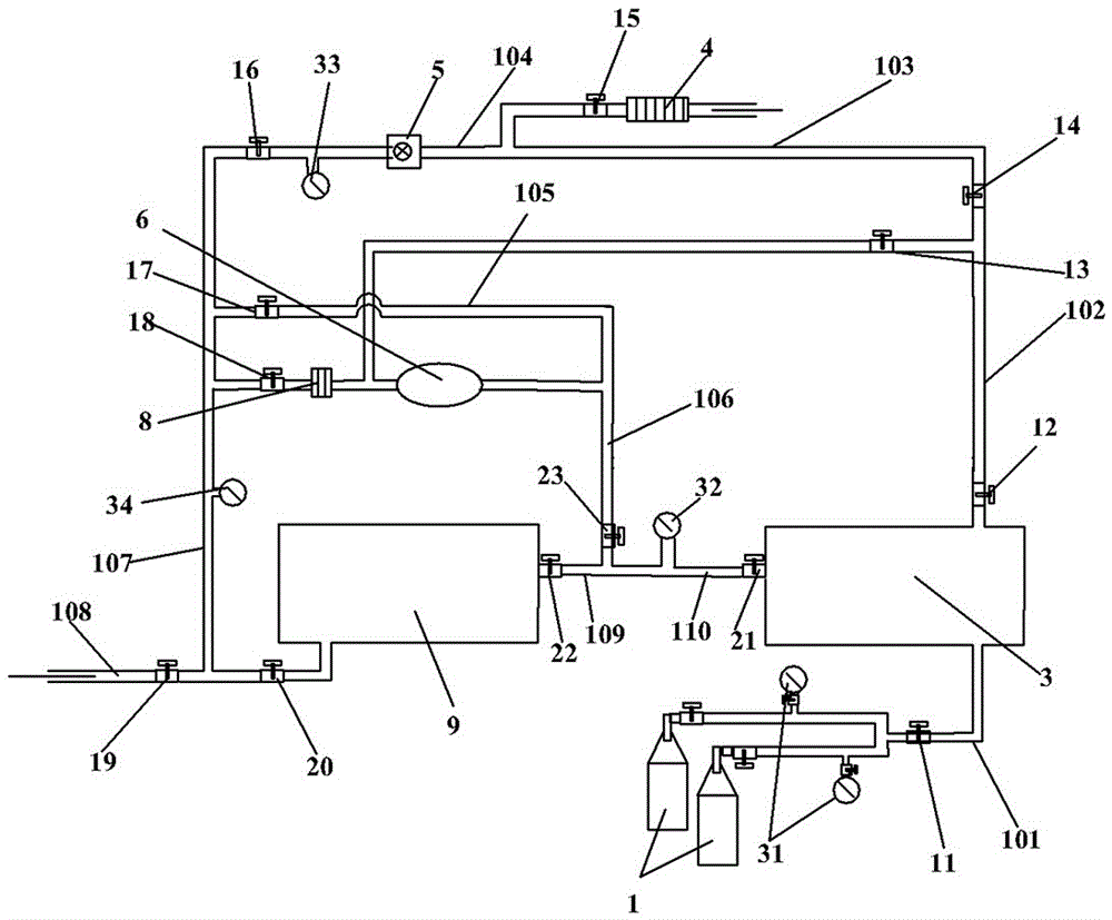
[0021] The specific embodiment of the gas mixing device provided by the present invention, such as figure 1 As shown, the gas mixing device in this embodiment includes a first gas storage tank 3 and a second gas storage tank 9 for storing the mixed gas, wherein the first gas storage tank 3 is connected with two gas storage tanks through an inflation pipeline 101 The source gas cylinder 1 is equipped with gas to be mixed in the two gas source cylinders, and an inflation control valve 11 is also arranged on the inflation pipeline 101, and a corresponding first gas flow meter 31 is configured to detect the two gas sources The gas flow rate that the gas cylinder 1 rushes into the first gas storage tank 3 .

[0022] In this embodiment, the gas mixing device includes an air compressor 6 with an air inlet and an air outlet. The air compressor 6 is not only use...


PUM


Abstract

The invention relates to a gas mixing device including an air compressor having a gas inlet and a gas outlet; the gas mixing device also includes a first gas storage tank and a second gas storage tank for storing mixed gas; the first gas storage tank is connected with the gas inlet of the air compressor through a first pipeline; the second gas storage tank is connected with the gas inlet of the air compressor through a second pipeline; the first gas storage tank communicates with the gas outlet of the air compressor through a third pipeline; the second gas storage tank communicates with the gas outlet of the air compressor through a fourth pipeline; a first control valve, a second control valve, a third control valve and a fourth control valve for controlling on-off of the corresponding pipelines are correspondingly arranged on the first pipeline, the second pipeline, the third pipeline and the fourth pipeline; the air compressor pumps gas in the first gas storage tank into the second gas storage tank through the first pipeline and the fourth pipeline and pumps gas in the second gas storage tank into the first gas storage tank through the second pipeline and the third pipeline. The gases in the two gas storage tanks are circulated by the air compressor, the mixing speed of the mixed gas can be effectively accelerated, and the mixing requirement is achieved in a short time without long-term standing.

Description

technical field [0001] The invention relates to a gas mixing device. Background technique [0002] With the rapid development of the power industry, people are eager to pursue the miniaturization design of high-voltage switches, which puts forward higher requirements for the insulation of power equipment. At present, the filling medium in high voltage switches mostly uses SF 6 gas, SF 6 Gases are widely used in the power industry because of their high insulation and arc extinguishing capabilities. However, SF 6 The gas has the following defects: first, the liquefaction temperature is high, and when used in the cold winter season in the alpine region, it is easy to liquefy, which poses a serious threat to the safe operation of power equipment; second, SF 6 The gas is a very strong greenhouse gas, and its GWP value is the equivalent of CO 2 23,900 times that of the Kyoto Protocol passed in 1997, the SF 6 The gas is listed as a gas that requires global control; third, it ...

Claims


Application Information

Patent Timeline
Patent Type & Authority Applications(China)
IPC IPC(8): G01N1/38B01F15/02B01F5/00B01F23/10
CPCG01N1/38G01N2001/386G01N2001/387B01F25/14B01F35/712B01F35/716
Inventor 林生军李永林李宝增孙清超赵晓民谢美芳李卫胜王彦良刘宗杰孔平周柏杰薛健庞博宋新利林莘
Owner PINGGAO GRP
Why Eureka
Try Eureka