Grouting material feeding device of shield machine

A technology of grouting materials and shield machines, which is applied in loading/unloading, transportation and packaging, mining equipment, etc. It can solve problems such as poor feeding of silos, increased number of times of transportation, and space restrictions, so as to reduce transportation load and cost, the effect of fewer times of material transportation, and the smooth discharge of materials

Inactive Publication Date: 2017-02-22
ZHENJIANG COLLEGE
View PDF6 Cites 1 Cited by
  • Summary
  • Abstract
  • Description
  • Claims
  • Application Information

AI Technical Summary

Problems solved by technology

[0002] When the shield machine is tunneling underground, the space in the diameter direction is strictly limited, while the space in the length direction is relatively large. Therefore, the feeding device for the grouting material can only be designed as a narrow and long structure
The existing grouting material feeding device of the shield machine adopts the setting form of single feeding port or double feeding port. The disadvantage of this device is that the feeding of the silo is not smooth, and the silo will not accumulate material without external disturbance. Too much, the ratio of accumulation to material is very high, which increases the number of materials transported per unit excavation length, and increases the transport load and cost of excavation tunnels

Method used


Image

  • Grouting material feeding device of shield machine
  • Grouting material feeding device of shield machine
  • Grouting material feeding device of shield machine

Examples


Embodiment Construction

[0018] The present invention will be further described in detail below in conjunction with the first embodiment of the accompanying drawings.

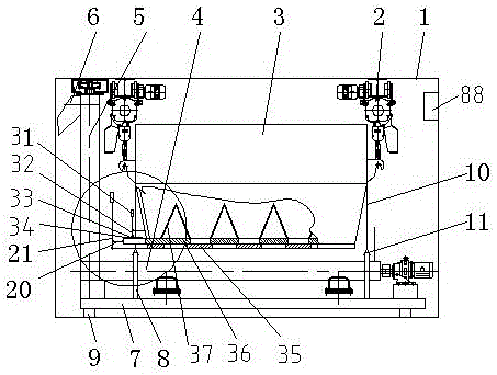
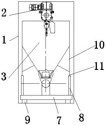
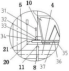
[0019] A shield machine grouting material feeding device, comprising a frame 1, a crane 2 connected to the top of the frame 1, a silo 3 connected to the crane 2, a material receiving screw conveyor 4, and a vertical screw conveyor 5 And the discharge port 6, the receiving screw conveyor 4 is located below the silo 3, the lower end of the vertical screw conveyor 5 is connected to the left side of the receiving screw conveyor 4, and the discharge port 6 is connected to the upper end of the vertical screw conveyor 5 , which is characterized in that the grouting material feeding device of the shield machine also includes a grid blanking device, a bin positioner and a weighing device. The grid blanking device is located at the bottom of the bunker 3 and is connected to the bunker 3. The silo locator is located below the silo 3 , the weighin...


PUM


Abstract

When a shield machine is carrying out tunneling, the space of the diameter direction of the shield machine is strictly limited, but the space of length direction is larger. Thus, a grouting material feeding device of shield machine can only be designed into a long and narrow structure. The grouting material feeding device of the shield machine in the invention compromises a body frame, a hoist which is connected with the top of the body frame, a bunker which is connected with the hoist, a receiving screw conveyer, a vertical screw conveyer and a discharge port. The grouting material feeding device of shield machine also comprises a grid plate unloader, a bunker locator and a weighing instrument. The grid plate unloader is positioned at the bottom of the bunker and connected with the bunker. The bunker locator is positioned below the bunker. The weighing instrument is positioned below the bunker locator. The receiving screw conveyer is arranged on the weighing instrument. The weighing instrument is arranged on the bottom surface of the body frame. The grouting material feeding device of shield machine solves the technical problems of too much accumulated material in the bunker and a high accumulated material ratio. The grouting material feeding device of shield machine has the advantages of being smooth in discharging material of the bunker, low in accumulated material ratio, less number of times in carrying material on the unit length of tunneling, and reducing the transportation load and cost of tunneling the tunnel.

Description

technical field [0001] The invention relates to a device for moving powder or granular material through a silo for a certain distance, and then discharging and transporting the material to a mixing device after reaching a destination, in particular to a shield machine grouting material feeding device. Background technique [0002] When the shield machine is tunneling underground, the space in the diameter direction is strictly limited, while the space in the length direction is relatively large. Therefore, the feeding device for the grouting material can only be designed as a narrow and long structure. The existing grouting material feeding device of the shield machine adopts the setting form of single feeding port or double feeding port. The disadvantage of this device is that the feeding of the silo is not smooth, and the silo will not accumulate material without external disturbance. More, the ratio of accumulation to material is very high, which increases the number of m...

Claims


Application Information

Patent Timeline
Patent Type & Authority Applications(China)
IPC IPC(8): E21D9/06B65G65/46
CPCE21D9/06B65G65/463
Inventor 陈兴和许星李镇明陈聪陈骁
Owner ZHENJIANG COLLEGE
Why Eureka
Try Eureka