Bladeless fan adopting turbine spiral air supply

A bladeless fan and screw-type technology, which is applied to components of pumping devices for elastic fluids, non-volume pumps, non-variable volume pumps, etc., can solve the problems of difficult cleaning of blades and outer covers, increased noise, and wind Unevenness and other problems, to avoid fan failure or even damage, prolong service life, clean and fresh airflow

Inactive Publication Date: 2017-02-22
QINZHOU UNIV
View PDF5 Cites 0 Cited by
  • Summary
  • Abstract
  • Description
  • Claims
  • Application Information

AI Technical Summary

Problems solved by technology

[0002] The existing fan drives the blades to rotate through the motor, and the air is pressurized and accelerated by the blades and then blows to the user, giving the user the feeling of blowing, but there are the following disadvantages: First, the rotating blades have a high speed, and if they accidentally touch It will cause harm, and most fans often use outer covers to surround the blades to reduce danger; second, the blades and outer covers are difficult to clean, and they need to be dried before they can be put back, which is troublesome and time-consuming; Noise, which brings disturbance to users; Fourth, because the airflow changes when passing through the surface of the blade, the wind blown out is uneven, and the user will feel similar to pulsed strong wind, or hot wind, and the comfort is poor
However, the disadvantage of the current bladeless fan is that the wind speed is small, there is no cooling function, and it cannot meet the basic requirements of users to enjoy the cool air. If the wind speed is increased, the noise will be increased (the wind speed is proportional to the noise), and the practicability is poor.

Method used


Image

  • Bladeless fan adopting turbine spiral air supply
  • Bladeless fan adopting turbine spiral air supply
  • Bladeless fan adopting turbine spiral air supply

Examples


Embodiment Construction

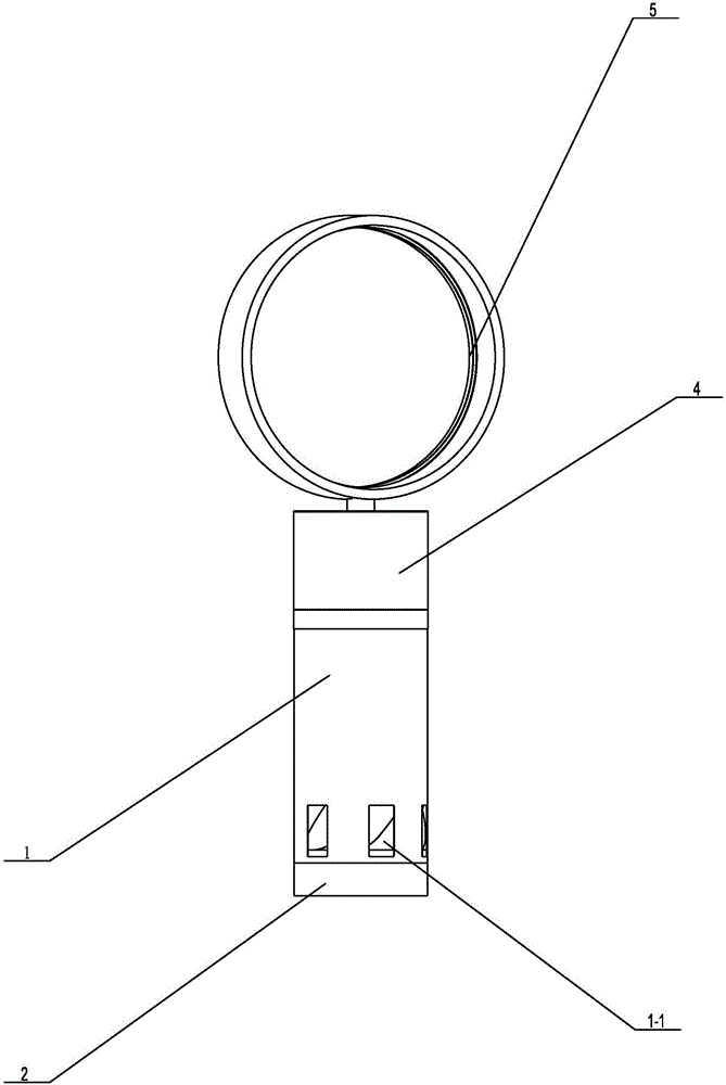
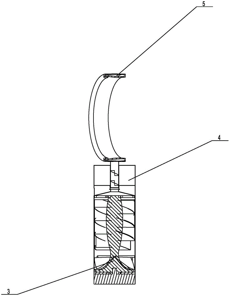
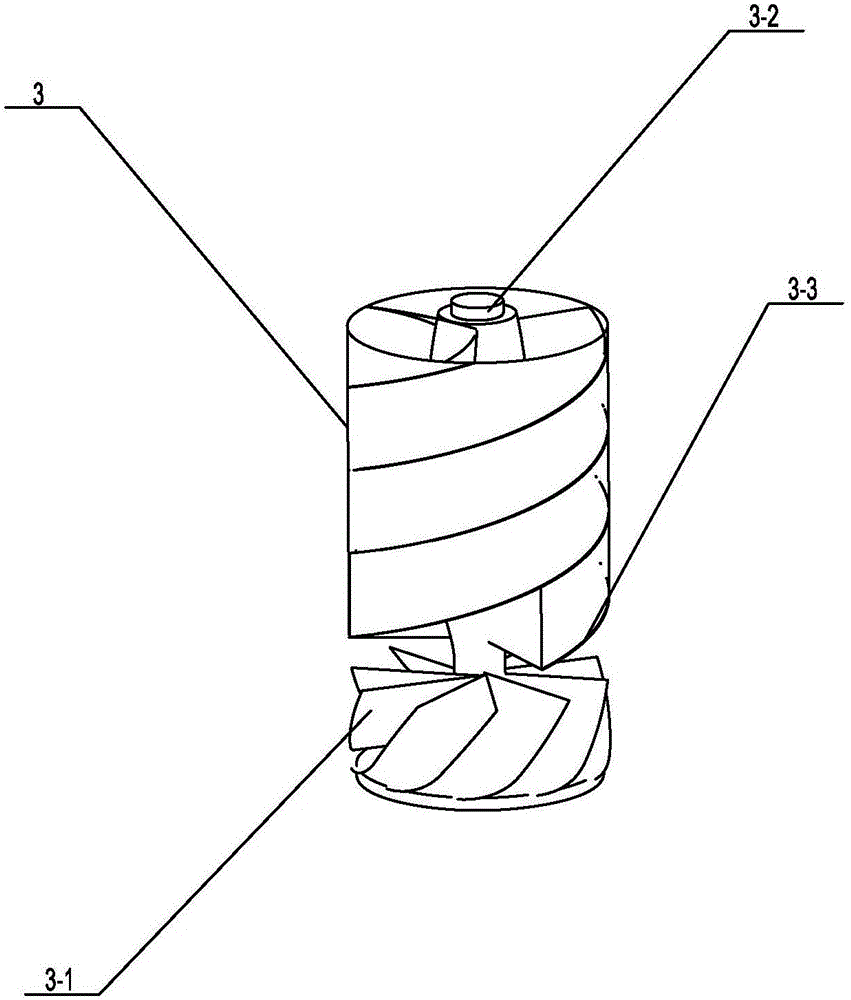
[0017] like figure 1 and figure 2 As shown, a specific embodiment of the present invention is proposed, using a bladeless fan with turbo spiral air supply, including a fan base 1, and a driving device 2 located below the fan base 1. In this embodiment, the driving device 2 is set to be an electric motor. Several air inlets 1-1 are provided on the fan base 1, and a turbo screw device 3 communicated with all the air inlets 1-1 is arranged in the fan base 1, and the turbo screw device 3 includes and communicates with all air inlets 1-1. A turbine 3-1 connected to the inlet and used for air suction, and the turbine 3-1 is connected to the driving device 2. The turbine 2 is provided with a fixed rod 3-2, and the two sides of the fixed rod 3-2 are provided with A number of helical sheets 3-3, such as image 3 As shown, the top of the fan base 1 is provided with a refrigeration device 4 that communicates with its interior and is used to cool the air flow. The structure of the refr...


PUM


Abstract

The invention provides a bladeless fan adopting turbine spiral air supply. The bladeless fan adopting turbine spiral air supply comprises a fan base and a driving device; the fan base is provided with a plurality of air inlets; the fan base is internally provided with a turbine spiral device communicated with the air inlets; a refrigerating device communicated with the interior of the fan base and used for cooling airflow is arranged above the fan base; and a round and hollow effect generator communicated with the interior of the refrigerating device is arranged above the refrigerating device. The fan base is internally provided with the turbine spiral device, air can be effectively absorbed and can also be fast supplied, and the defect that the existing air speed is small is changed; the refrigerating device is arranged, the air draught is effectively lowered, and therefore cold air can be supplied to a user, and the requirement that the user enjoys the cool is met; and the effect generator is arranged, the cold air can be continuously and unceasingly supplied, use is comfortable, practicability is good, and the bladeless fan adopting turbine spiral air supply is worthy of wide popularization.

Description

technical field [0001] The invention relates to the field of household appliances, in particular to a bladeless fan adopting a turbo spiral air supply. Background technique [0002] The existing fan drives the blades to rotate through the motor, and the air is pressurized and accelerated by the blades and then blows to the user, giving the user the feeling of blowing, but there are the following disadvantages: First, the rotating blades have a high speed, and if they accidentally touch It will cause harm, and most fans often use outer covers to surround the blades to reduce danger; second, the blades and outer covers are difficult to clean, and they need to be dried before they can be put back, which is troublesome and time-consuming; Noise brings disturbance to the user; Fourth, because the airflow changes when passing through the surface of the blade, the wind blown out is not uniform, and the user will feel similar to pulsed strong wind or hot wind, and the comfort is poo...

Claims


Application Information

Patent Timeline
Patent Type & Authority Applications(China)
IPC IPC(8): F04B41/06F04D29/28F04D29/58F04D29/70F04F5/16F04F5/44
CPCF04B41/06F04D29/281F04D29/582F04D29/703F04F5/16F04F5/44
Inventor 孙腾潘宇晨梁汉福秦闻新
Owner QINZHOU UNIV
Why Eureka
Try Eureka