Proximity switch for oil cylinder

A technology of a proximity switch and an oil cylinder, which is applied in fluid pressure actuators, servometer circuits, and fluid pressure actuator system tests, etc. It can solve the problems of difficult axial position, poor interchangeability, and easy change of the position of the probe 10, etc. Accurate axial positioning, easy installation and good interchangeability

Inactive Publication Date: 2017-02-22
泸州合成液压件有限公司
View PDF0 Cites 2 Cited by
  • Summary
  • Abstract
  • Description
  • Claims
  • Application Information

AI Technical Summary

Problems solved by technology

[0002] In order to accurately control the position of the piston in the oil cylinder, a proximity switch is often set on the cylinder; the existing oil cylinder uses a proximity switch such as figure 1 As shown, the protective cover 8, the mounting base 9, and the probe 10 placed in the two, the position of the probe 10 in the axial direction is related to the accuracy of its detection. In order to control its axial position, two threads are provided on the probe 10. The adjustment nut 11, the lower adjustment nut is in contact with the installation base 9; the disadvantages of this structure are: 1) It is difficult to adjust the axial position of the probe 10 through the two adjustment nuts 11, which cannot be completed by non-professionals, and the interchangeability is also poor; 2) When the oil cylinder is subjected to high pressure, it will vibrate, the two adjusting nuts 11 are easy to loosen, and the position of the probe 10 is easy to change, so it is difficult to ensure normal operation; 3) The working status of the proximity switch cannot be displayed, and the operator cannot monitor the fault.

Method used


Image

  • Proximity switch for oil cylinder
  • Proximity switch for oil cylinder

Examples


Embodiment Construction

[0010] The present invention will be described in further detail below in conjunction with the accompanying drawings.

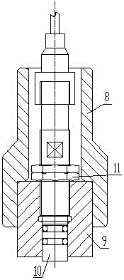
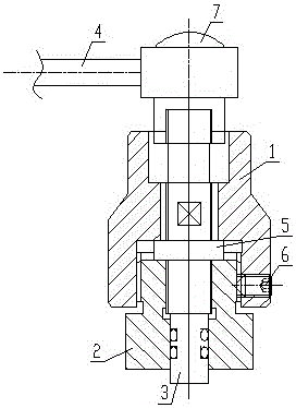
[0011] Such as figure 2 As shown, the proximity switch for an oil cylinder in this embodiment includes a protective cover 1, a mounting base 2, a probe 3 placed in the two, and a connecting wire 4 connected to the rear end of the probe 3; the protective cover 1 is provided with a stepped hole, and the probe There is a shoulder 5 in the middle of 3, and the mounting base 2 is connected with the protective cover 1 through threads and radial set screws 6. The probe 3 is located in the inner hole of the protective cover 1 and the mounting base 2, and the shoulder 5 of the probe 3 is stuck on the Between the end face of the stepped hole of the protective cover 1 and the rear end face of the installation base 2; the connecting line 4 at the rear end of the probe 3 is provided with an LED indicator 7;

[0012] In the present invention, since the probe 3 is pressed...


PUM


Abstract

The invention discloses a proximity switch for an oil cylinder. The proximity switch comprises a protective sleeve, a mounting base, a probe arranged in the protective sleeve and the mounting base, and a connecting line connected with the rear end of the probe. The proximity switch for the oil cylinder is characterized in that the protective sleeve is provided with a stepped hole; a shaft shoulder is arranged in the middle of the probe; the mounting base and the protective sleeve are connected through a thread and a radial set screw; the probe is located in inner holes of the protective sleeve and the mounting base; and the shaft shoulder of the probe is clamped between the end face of the stepped hole of the protective sleeve and the rear end face of the mounting base. The proximity switch for the oil cylinder has the advantages of being easy and convenient to mount, good in interchangeability, resistant to high pressure and not prone to loosening. The normal work can be guaranteed, and the working state of the proximity switch can be monitored.

Description

technical field [0001] The invention relates to a proximity switch for an oil cylinder. Background technique [0002] In order to accurately control the position of the piston in the oil cylinder, a proximity switch is often installed on the cylinder; the existing oil cylinder uses a proximity switch such as figure 1 As shown, the protective cover 8, the mounting base 9, and the probe 10 placed in the two, the position of the probe 10 in the axial direction is related to the accuracy of its detection. In order to control its axial position, two threads are provided on the probe 10. The adjustment nut 11, the lower adjustment nut is in contact with the installation base 9; the disadvantages of this structure are: 1) It is difficult to adjust the axial position of the probe 10 through the two adjustment nuts 11, which cannot be completed by non-professionals, and the interchangeability is also poor; 2) When the oil cylinder is subjected to high pressure, it will vibrate, the ...

Claims


Application Information

Patent Timeline
Patent Type & Authority Applications(China)
IPC IPC(8): F15B15/28F15B19/00
CPCF15B15/2807F15B19/005F15B2211/87F15B2215/30
Inventor 丁运全
Owner 泸州合成液压件有限公司
Why Eureka
Try Eureka