Monitoring method for control valve failure based on DCS data

A technology for controlling valves and data, applied to valve devices, mechanical equipment, engine components, etc., can solve problems such as difficult processes and high costs, and achieve the effects of ensuring monitoring effects, reducing monitoring costs, and reliable monitoring effects

Active Publication Date: 2017-02-22
BEIJING UNIV OF CHEM TECH
View PDF6 Cites 4 Cited by
  • Summary
  • Abstract
  • Description
  • Claims
  • Application Information

AI Technical Summary

Problems solved by technology

Installing additional digital valve positioners is technically difficult and expensive
[0004] Distributed Control System (DCS) is a comprehensive control system that emerged with the continuous rise of modern large-scale industrial production automation and the increasingly complex requiremen

Method used


Image

  • Monitoring method for control valve failure based on DCS data
  • Monitoring method for control valve failure based on DCS data
  • Monitoring method for control valve failure based on DCS data

Examples


Embodiment Construction

[0052] Such as Figure 5 As shown, the flow control valve monitoring method based on DCS data of the present invention includes the following steps,

[0053] Step 1: Obtain valve DCS data as training data, classify the training data according to different working conditions, and establish valve models for temperature valves, liquid level valves, pressure valves, and flow valves.

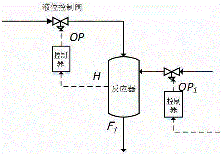
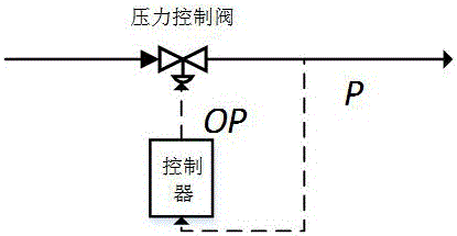
[0054] Valve controller measurements are available from the DCS database ,output value ,in, represents the valve opening, The meaning of the representative varies with the valve: for the flow valve, represents the flow value F ; for temperature valves, represents the temperature value ; For level valves, Represents the liquid level value H ; For pressure valves, represents the pressure value P .

[0055] To establish the valve models of temperature valves and liquid level valves, refer to the process drawings. Due to the pressure value of the pressure valve and the flow value ...


PUM


Abstract

The invention relates to a monitoring method for a control valve failure based on DCS data. The method is characterized by comprising the following steps: 1) taking DCS data of a valve as training data, classifying the training data according to different working conditions and establishing valve models for a temperature valve, a liquid level valve, a pressure valve and a flow valve; 2) confirming the corresponding valve models under different working conditions on the basis of the training data; 3) identifying the current working condition and confirming the corresponding valve model under the current working condition; 4) forecasting the valve state value according to the valve model confirmed in the step 3); 5) judging the failure according to the practical state value of the valve and the corresponding estimated state value.

Description

technical field [0001] The invention relates to a control valve fault monitoring method based on DCS data. Background technique [0002] Control valves (temperature valves, liquid level valves, pressure valves, and flow valves) are the most widely used terminal control components in industrial automation production, especially in chemical production processes. It is also a relatively weak link in technology for a long time. Once the control valve fails, the control loop will be forced to interrupt the control operation, which may cause a larger system failure, cause the device to shut down and cause incalculable economic losses. However, in the actual production process, operators cannot monitor the control valves in real time, and can only perform preventive maintenance on important valves during planned maintenance. Such a maintenance method has a long cycle, blindness, untimelyness, low efficiency, and high time and personnel costs. [0003] Digital valve positioners h...

Claims


Application Information

Patent Timeline
IPC IPC(8): F16K37/00
CPCF16K37/00
Inventor 王友清楼志江脱建勇
Owner BEIJING UNIV OF CHEM TECH
Why Eureka
Try Eureka