
Heat pump system and car with same

A technology of heat pump system and heat exchanger, which is applied in the field of automobiles, can solve the problems of low heat exchange efficiency and single flow direction of refrigerant, and achieve the effect of improving heat exchange efficiency

Inactive Publication Date: 2017-02-22
GREE ELECTRIC APPLIANCES INC
View PDF6 Cites 4 Cited by
  • Summary
  • Abstract
  • Description
  • Claims
  • Application Information

AI Technical Summary

Problems solved by technology

[0018] Therefore, the technical problem to be solved by the present invention is to overcome the problem that the refrigerant expanded by the third expansion valve is exchanged from the second heat exchanger in the prior art no matter in heating or cooling. The heat inlet enters the second heat exchanger and flows out of the second heat exchanger from the heat exchange outlet of the second heat exchanger, resulting in a single flow direction of this part of the refrigerant in the second heat exchanger, which in turn leads to a This part of the refrigerant flows in the same direction as the other part of the refrigerant flowing through the second heat exchanger, resulting in a technical defect of low heat exchange efficiency, thereby providing a method that can change the flow direction of the part of the refrigerant in the second heat exchanger, and then Heat pump system to improve heat exchange efficiency

Method used


Image

  • Heat pump system and car with same
  • Heat pump system and car with same
  • Heat pump system and car with same

Examples


Embodiment 1

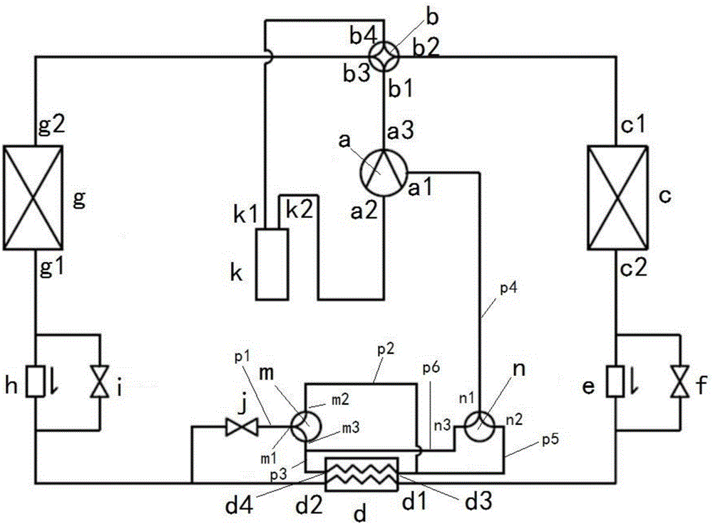
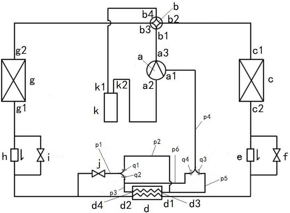
[0066] This embodiment provides a heat pump system, such as figure 2 shown, including:

[0067] A compressor a has a first compressor inlet a1, a second compressor inlet a2 and a compressor outlet a3;

[0068] The four-way structure b has a first opening b1, a second opening b2, a third opening b3 and a fourth opening b4, the first opening b1 communicates with the compressor outlet a3, the fourth opening b4 communicates with the The second compressor inlet a2 is in communication; the four-way structure b has a first state in which the first opening b1 is in communication with the second opening b2, and the third opening b3 is in communication with the fourth opening b4 , and a second state in which the first opening b1 communicates with the third opening b3, and the second opening b2 communicates with the fourth opening b4;

[0069] a first heat exchanger c, having a first heat exchanger inlet c1 communicating with said second opening b2, and a first heat exchanger outlet c...

Embodiment 2

[0109] This embodiment provides an automobile installed with the heat pump system described in Embodiment 1.

[0110] The automobile in this embodiment, since the heat pump system in Embodiment 1 is installed, naturally has all the advantages brought by the installation of the above heat pump system.


PUM


Abstract

The invention provides a heat pump system and a car with the same. The heat pump system comprises a compressor, a four-way structure, a first heat exchanger, a second heat exchanger, a first one-way valve, a first expansion valve, a third heat exchanger, a second one-way valve, a second expansion valve and a third expansion valve; one end of the third expansion valve communicates with a pipe part communicating with a second heat exchanger outlet, the second one-way valve and the second expansion valve simultaneously, and the other end of the third expansion valve is communicated with a control structure; and the control structure receives refrigerants coming from the third expansion valve, inputs the refrigerants into a second heat exchange route of the second heat exchanger and enables the flowing direction of the refrigerants in the second heat exchange route to be opposite to the flowing direction of refrigerants directly input into a first heat exchange route of the second heat exchanger. According to the heat pump system, it can be guaranteed that the flowing direction of the refrigerants flowing in the second heat exchange route is opposite to the flowing direction of the refrigerants flowing in the first heat exchange route all the time both in the heating state or the refrigeration state, and the heat exchange efficiency of the second heat exchanger is improved.

Description

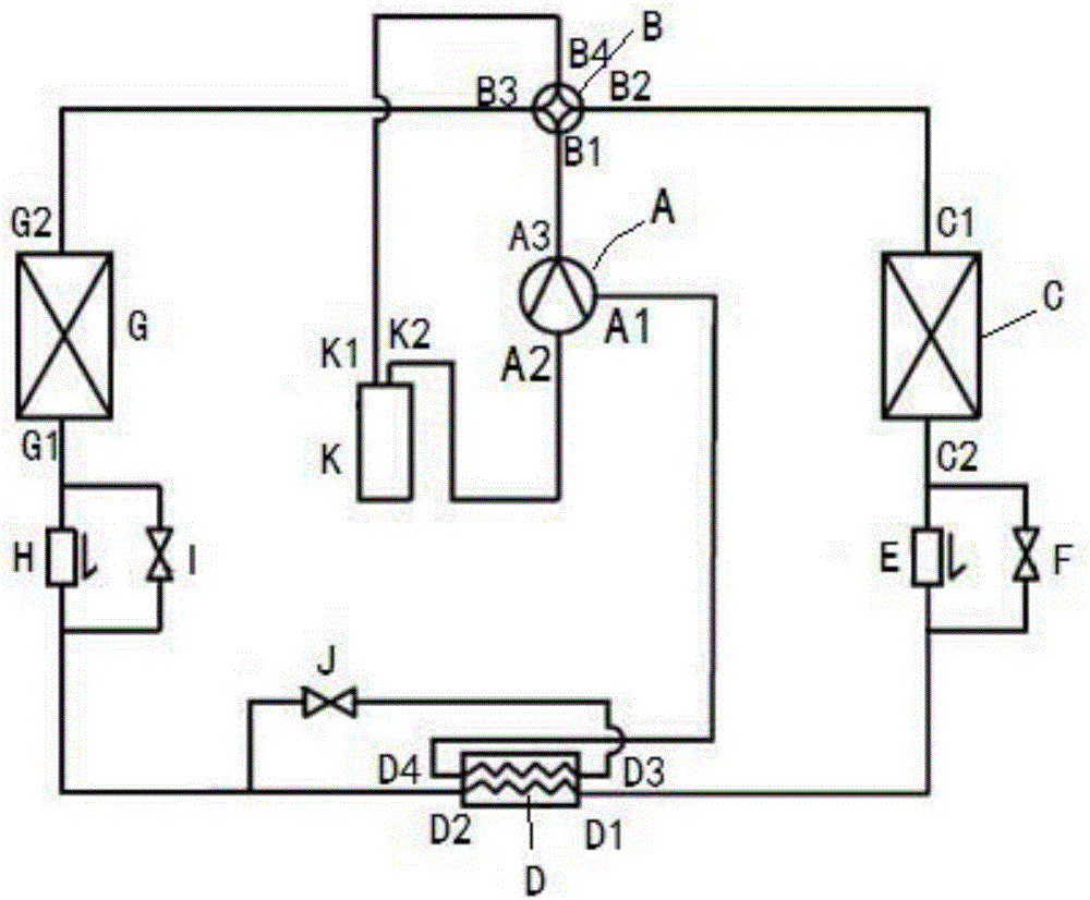
technical field [0001] The invention relates to the technical field of heat pump systems, in particular to a heat pump system applied to pure electric vehicles and a vehicle equipped with the same. Background technique [0002] With the rapid development of new energy vehicles, pure electric vehicles have begun to occupy more and more market share. Pure electric vehicles have no engine waste heat to use, and generally use a heat pump system as a temperature control system. Among them, a throttling two-stage compression heat pump system is a more commonly used heat pump system. The heat pump system can be used for both cooling and heating. . [0003] The primary throttling two-stage compression heat pump system in the prior art is as figure 1 shown, including: [0004] A compressor A having a compressor outlet A3, a first compressor inlet A1 and a second compressor inlet A2; [0005] The four-way valve B has a first opening B1, a second opening B2, a third opening B3 and ...

Claims


Application Information

Patent Timeline
IPC IPC(8): F25B13/00F25B41/04F25B43/00F25B41/20F25B41/31
CPCF25B13/00F25B43/006F25B2313/02732F25B2500/09F25B41/22
Inventor 梁尤轩赵桓谭锋卢耀汕沈军
Owner GREE ELECTRIC APPLIANCES INC
Learn More