Movable slagging chute for smelting furnace

A smelting furnace and chute technology, applied in the chute field, can solve problems such as being easily affected by high-temperature hot slag, not easy to replace and maintain, and difficult to rotate, so as to increase the driving torque, reduce the impact, and reduce maintenance costs.

Inactive Publication Date: 2017-02-22
HUNAN SHUI KOU SHAN NONFERROUS METALS GRP
View PDF5 Cites 5 Cited by
  • Summary
  • Abstract
  • Description
  • Claims
  • Application Information

AI Technical Summary

Problems solved by technology

[0003] 1. Use multi-section chute splicing, as attached figure 1 As shown, the structure is complex and heavy, and it is not easy to replace and maintain;
[0004] 2. The pusher is designed beside the chute, if attached figure 2 As shown, it is easily affected by high-temperature hot slag, and the failure rate is high;
The direction of the chute in the converter alloy chute is changed by the rotation of the alloy container, and the rotation operation is difficult

Method used


Image

  • Movable slagging chute for smelting furnace
  • Movable slagging chute for smelting furnace
  • Movable slagging chute for smelting furnace

Examples


Embodiment Construction

[0023] The present invention will be further described below in conjunction with the accompanying drawings and embodiments.

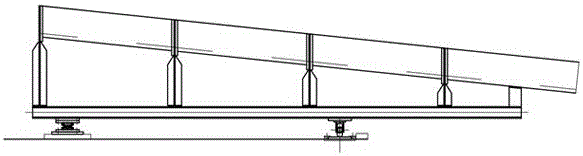
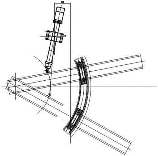
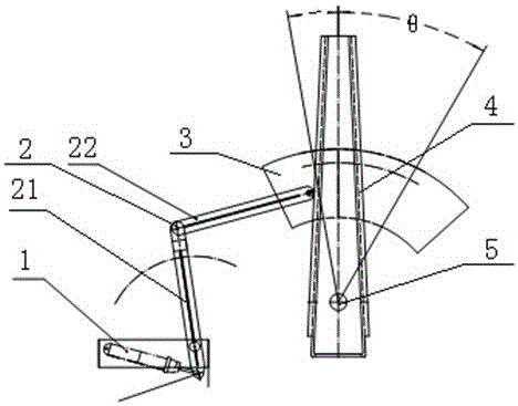
[0024] refer to image 3 and 4 : A kind of movable slagging chute for smelting furnace, comprising pusher 1, push rod 2, movable chute 4, rotating seat 5, roller 9, rotating shaft 51 frame 6; shown movable chute 4 is integral structure, shown movable chute There is a rotating seat 5 under one end of the 4, and a roller 9 is provided under the end away from the rotating seat 5. The roller 9 is installed on the chute wheel rail 3, and drives the movable chute 4 along the chute wheel rail under the push of the push rod 2. 3 to move; the movable chute 4 is provided with a rotating shaft 51 frame 6.

[0025] Described push rod 2 is a link mechanism, is made up of first connecting rod 21 and second connecting rod 22, and described first connecting rod 21 is connected with pusher 1 and an end of second connecting rod 22; The other end of bar 22 is connected...


PUM


Abstract

The invention relates to a movable slagging chute for a smelting furnace. The movable slagging chute comprises a propeller, a push rod, a movable chute, a rotating base, an idler wheel and a rotating shaft frame, wherein the movable chute has an integrated structure; a rotating base is arranged under one end of the movable chute; the idler wheel is arranged under the other end of the movable chute away from the rotating base; the idler wheel is arranged on a chute wheel rail and is capable of driving the movable chute to move on the chute wheel rail under the driving of the push rod; the rotating shaft frame is arranged on the movable chute. The movable slagging chute for the smelting furnace can realize the connection between the propeller and the movable chute by adopting the push rod structure; the influence of high-temperature slag on the propeller is reduced; the problems of high fault rate and low reliability of the movable slagging chute for slagging at a slag port of the smelting furnace are solved; the safe and reliable slagging operation is ensured; the integrated movable chute is adopted, so that the loading capacity of the chute is increased, the service life is prolonged and the motion of the movable chute is benefited.

Description

technical field [0001] The invention relates to a chute, in particular to a movable slag discharge chute for a smelting furnace. Background technique [0002] Because the hot slag of the smelting furnace needs to be loaded into the next process by slag packs, usually one slag pack cannot be fully loaded, so a movable chute is needed to distribute the slag volume to the slag packs. The movable chute for discharging slag at the slag outlet of the smelting furnace is transporting hot slag, the temperature reaches above 1000 degrees Celsius, and the working condition is harsh. Slagging operation. The existing movable chute has the following defects. [0003] 1. Use multi-section chute splicing, as attached figure 1 As shown, the structure is complex and heavy, and it is not easy to replace and maintain; [0004] 2. The pusher is designed beside the chute, if attached figure 2 As shown, it is easily affected by high-temperature hot slag, and the failure rate is high; [00...

Claims


Application Information

Patent Timeline
Patent Type & Authority Applications(China)
IPC IPC(8): F27D3/15
CPCF27D3/15
Inventor 凡杰徐旭东陈学兴阳卫国伍建国尹晓君
Owner HUNAN SHUI KOU SHAN NONFERROUS METALS GRP
Why Eureka
Try Eureka