

Zero sequence current difference polarity comparison based power distribution network fault line selection method
A distribution network fault and zero-sequence current technology, which is applied to the fault location, detects faults according to the type of conductor, and measures electricity. It can solve problems such as potential safety hazards in the distribution network, and achieve low sampling frequency and simple and accurate line selection principles. high degree of effect
- Summary
- Abstract
- Description
- Claims
- Application Information
AI Technical Summary
Problems solved by technology
Method used
Image


Examples
Embodiment 1
[0021] Example 1: A method for fault line selection in a distribution network based on the comparison of the zero sequence current differential polarity. A simulation model is built according to the parameters of the distribution network. By setting different lines and phase single-phase ground faults in the simulation model, Obtain the line power frequency zero sequence current signal i generated by each simulated line under ground fault 0i (t); select the zero sequence current i within 10ms after the fault 0i (t); Then define the zero sequence current difference function F of the line i (t), find the zero sequence current i 0i (t) difference function F i (t), and then use the difference function F i (t) Construct P i (t), using P i (t) Compare the polarity of the zero sequence current of each line, when P i (t)=max{P 1 (t),P 2 (t)...,P n (t)}, then line i is a faulty line; when P i (t)≠max(P 1 (t),P 2 (t)...,P n (t)}, then i is a non-faulty line.
[0022] The specific steps are: ...
Embodiment 2
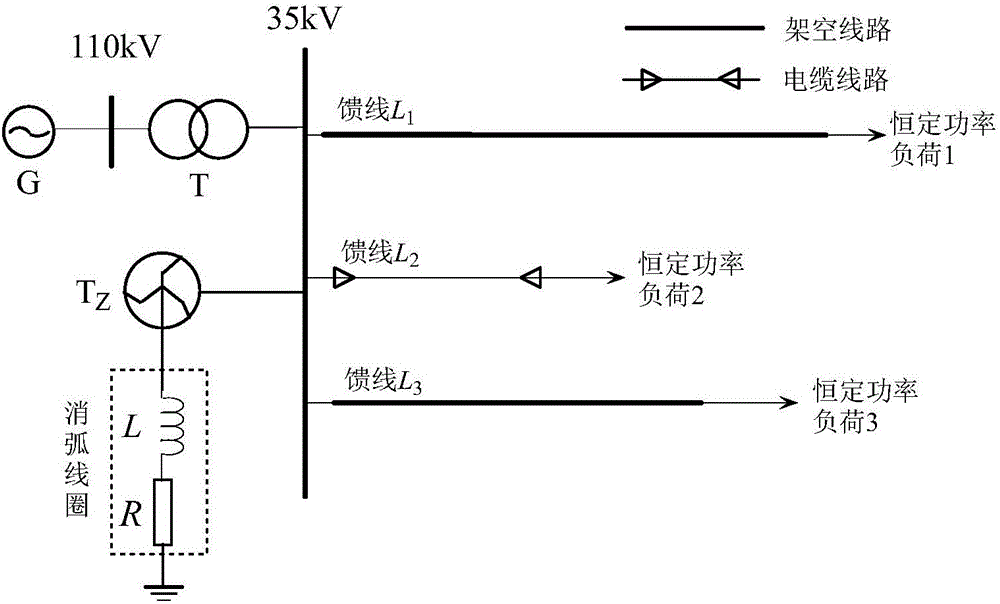
[0035] Embodiment 2: The other parts of this embodiment are the same as those of embodiment 1, such as figure 1 As shown, the 110kV / 35kV distribution network simulation model is as figure 1 As shown, it has 6 feeders, and the neutral point of the Z-shaped transformer is grounded through a series resistance of the arc suppression coil. Overhead feeder L 1 =18km, L 3 =30km, cable feeder L 2 = 7km. The G in the grid is an infinite power source; T is the main transformer, the transformation ratio is 110kV / 35kV, and the connection group is Y N / d11; T Z It is a zigzag transformer; L is the arc suppression coil; R is the damping resistance of the arc suppression coil. The feeder adopts three lines: overhead line, overhead line-cable hybrid line and cable line. The load uses a constant power load model.
[0036] (1) Feeder L 2 A single-phase ground fault occurred in phase B at a distance of 10 kilometers from the starting end, the ground resistance was 10Ω, the fault angle was 60°, a...
PUM
 Abstract
Description
Claims
Application Information