Linearity testing method for current sensor

A technology of current sensor and testing method, applied in the field of sensor testing, can solve problems such as difficulty, inability to obtain DCCT linearity, etc., and achieve the requirements of reducing accuracy and linearity, reducing linearity requirements, and avoiding resistance error and temperature error. Effect

Active Publication Date: 2017-02-22
SHANGHAI INST OF APPLIED PHYSICS - CHINESE ACAD OF SCI +1
View PDF4 Cites 10 Cited by
  • Summary
  • Abstract
  • Description
  • Claims
  • Application Information

AI Technical Summary

Problems solved by technology

Under such conditions, it is very difficult to test the DCCT with a linearity of 1ppm according to the conventional method. The me

Method used


Image

  • Linearity testing method for current sensor
  • Linearity testing method for current sensor
  • Linearity testing method for current sensor

Examples


Embodiment Construction

[0035] According to the attached Figure 1-Figure 2 , give a preferred embodiment of the present invention, and give a detailed description, so that the functions and characteristics of the present invention can be better understood.

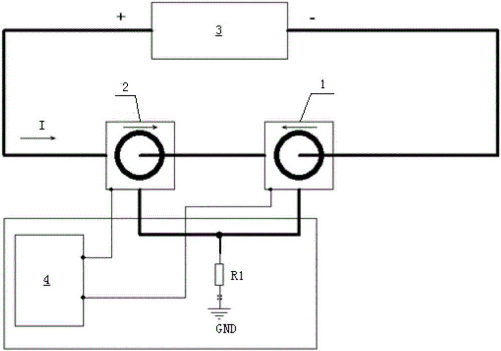
[0036] see figure 1 and figure 2 , a linearity testing method of a current sensor of the present invention, comprising steps:

[0037] S1: Construct a test system, the test system includes a standard current sensor 1, a current sensor to be tested 2, a load resistance R1, a DC source 3 and a power supply 4, wherein the standard current sensor 1 and the current sensor to be tested 2 The output end of the load resistance R1 is connected to the first end of the load resistance R1, and the second end of the load resistance R1 is grounded; the standard current sensor 1 and the current sensor 2 to be tested are connected in reverse series on the output circuit of the DC source 3, and the power supply 4 is respectively connected to the standard Cur...


PUM


Abstract

The invention provides a linearity testing method for a current sensor. The method comprises the steps that 1, a testing system is constructed; 2, a same power supply is provided for a standard current sensor and the to-be-tested current sensor, and currents with the opposite directions are introduced into the standard current sensor and the to-be-tested current sensor respectively; 3, the voltage of a load resistor is collected to obtain N groups of voltage data; 4, data processing is conducted on the voltage data, and a fitting line segment is obtained through a least square method; 5, relative linearity data of the to-be-tested current sensor and the standard current sensor is obtained through calculation; 6, the to-be-tested linearity data of the to-be-tested current sensor is obtained through calculation. According to the linearity testing method for the current sensor, the linearity requirement on a direct-current source is reduced in the testing process, resistance value errors and temperature errors of the load resistor are avoided, the requirements on the precision and the linearity of experimental equipment are greatly reduced, and the advantages of being high in precision and convenient to operate are achieved.

Description

technical field [0001] The invention relates to the field of sensor testing, in particular to a method for testing the linearity of a current sensor. Background technique [0002] The performance index of the power supply for various magnets of the synchrotron radiation device directly affects the realization of the physical requirements of the accelerator and its stable operation. In order to meet the high-performance index of the magnet power supply, a high-precision DC current sensor (DCcurrent transducer, DCCT) is used as the current feedback element. The accuracy, stability, linearity, temperature coefficient, bandwidth and other indicators of the DCCT directly determine the magnet power supply. performance. [0003] A high-performance DCCT requires a linear relationship between its input and output, good repeatability and stability, and is not affected by temperature and external magnetic field. The higher the linearity, the better the sensor tracking performance. L...

Claims


Application Information

Patent Timeline
IPC IPC(8): G01R35/00
CPCG01R35/00
Inventor 朱燕燕卢宋林李瑞王东兴胡志敏
Owner SHANGHAI INST OF APPLIED PHYSICS - CHINESE ACAD OF SCI
Why Eureka
Try Eureka