
Image forming apparatus

An image and equipment technology, applied in the field of image forming equipment, to achieve the effect of reducing scratches, improving brightness, and reducing color changes

Active Publication Date: 2017-02-22
FUJIFILM BUSINESS INNOVATION CORP
View PDF5 Cites 0 Cited by
  • Summary
  • Abstract
  • Description
  • Claims
  • Application Information

AI Technical Summary

Problems solved by technology

When successively fixing metallic toner images to multiple recording media, scratches on the heating member may become deeper and wider

Method used


Image

  • Image forming apparatus
  • Image forming apparatus
  • Image forming apparatus

Examples


Embodiment Construction

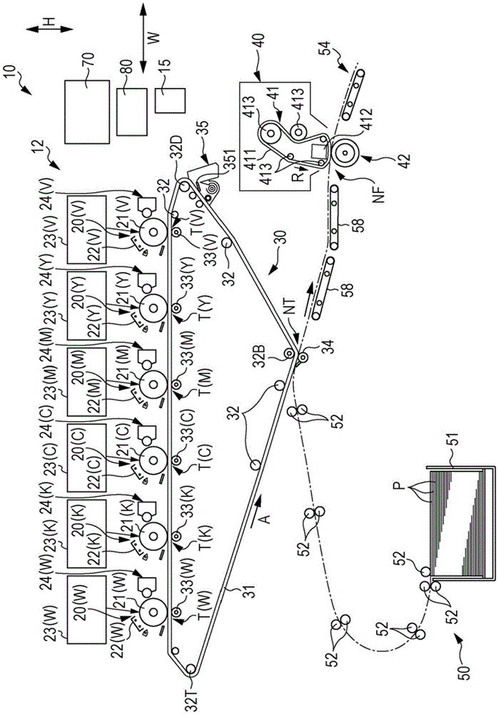
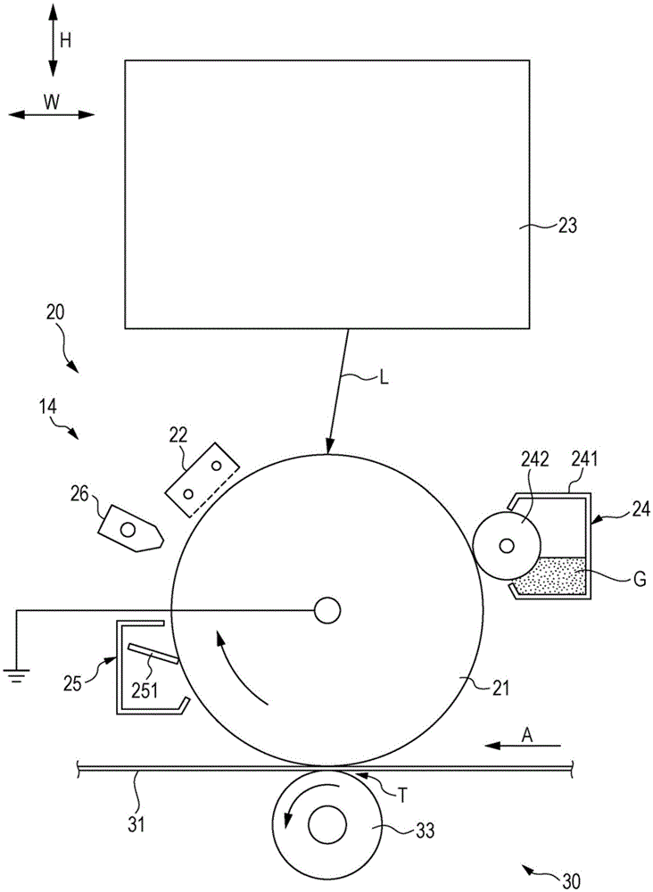
[0029] An image forming apparatus according to an exemplary embodiment of the present invention is described below. In the drawings, the double-headed arrow H indicates the vertical direction, and the double-headed arrow W indicates the horizontal direction, which is the width direction of the device.

[0030] Structure of Image Forming Device

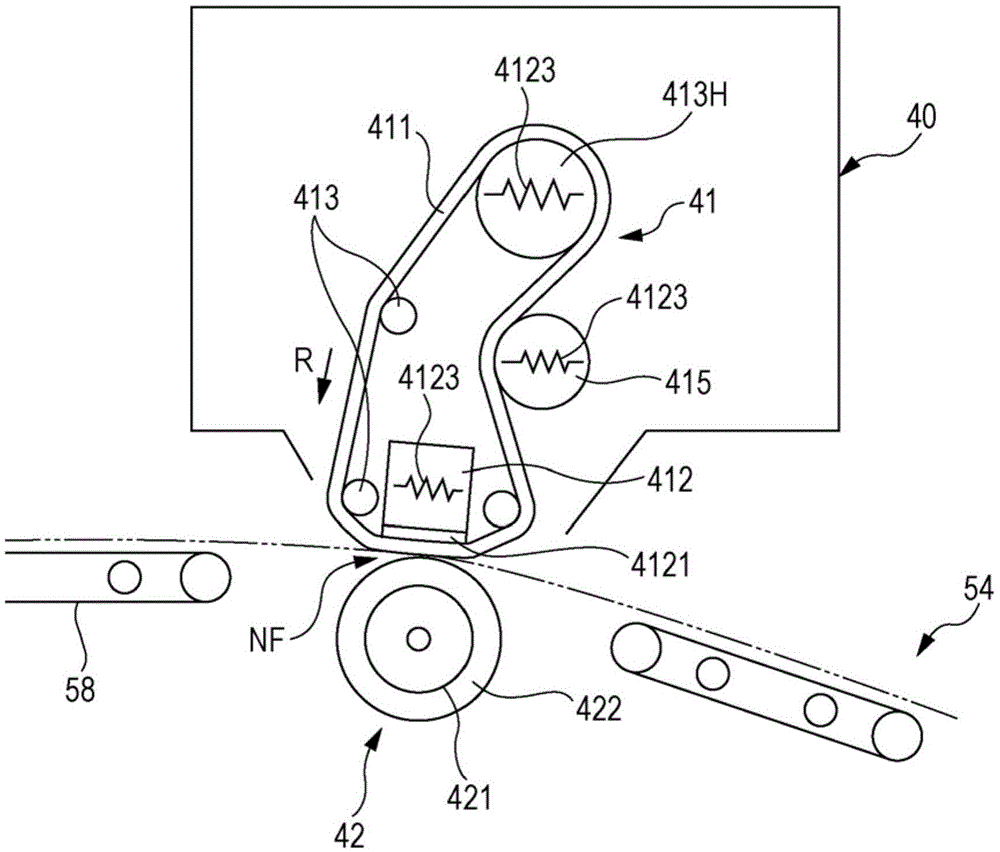
[0031] figure 1 is a schematic view of the structure of the image forming apparatus 10 as seen from the front. Such as figure 1 As shown in , the image forming apparatus 10 includes an image forming device 12 , a conveying device 50 , a controller 70 and a power supply device 80 . The image forming device 12 performs an electrophotographic system on a sheet-like surface PA of a sheet-like recording medium (sheet-like member) P such as paper (see, for example, Figure 5A , Figure 5B with Image 6 ) to form an image. The transport device 50 transports the recording medium P. As shown in FIG. The controller 70 controls the operat...


PUM


Abstract

An image forming apparatus includes a first image forming unit that forms a transparent toner image by using a transparent toner, a second image forming unit that forms a metal-colored toner image by using a metal-colored toner containing a flat metallic pigment, and a fixing device that fixes a toner image to a recording medium as a result of a heating member contacting and heating the toner image. The image forming apparatus has a mode in which the transparent toner image is superimposed upon the metal-colored toner image, and the toner images are fixed by the fixing device.

Description

technical field [0001] The present invention relates to image forming apparatuses. Background technique [0002] Japanese Unexamined Patent Application Publication No. 2006-317632 discloses a technology related to an image forming apparatus that performs a golden toner image to be developed at a photoconductor and a de-golden toner developed at a photoconductor. After toner images of colors other than the toner image are superimposed on the image carrier, these toner images are fixed to form an image. This prior art is characterized in that a gold toner image is superimposed on a toner image of a different color at the image carrier. [0003] Japanese Unexamined Patent Application Publication No. 2014-235381 discloses an image forming apparatus including: a first forming unit that forms a first image by using a first toner containing a flat pigment; a second a forming unit that forms a second image by using a second toner that does not contain a flat pigment; and a fixing ...

Claims


Application Information

Patent Timeline
IPC IPC(8): G03G15/00
CPCG03G15/6585G03G15/0126G03G15/0189G03G15/205G03G15/0105
Inventor 津田谕
Owner FUJIFILM BUSINESS INNOVATION CORP
Learn More