Visual significance detection method based on self-learning characteristics and matrix low-rank recovery

A detection method and feature matrix technology, which are applied in character and pattern recognition, image data processing, instruments, etc., can solve the problems of information redundancy, waste of computing resources, and effectiveness, so as to avoid redundancy, improve sparsity, and save computing. The effect of resources

Active Publication Date: 2017-02-22
ZHENGZHOU UNIVERSITY OF LIGHT INDUSTRY
2 Cites 2 Cited by

AI-Extracted Technical Summary

Problems solved by technology

The first type of feature extraction method usually uses multiple feature extraction operators while ensuring the feature integrity of the detected input image, but there is a large amount of information redundancy between these feature operators, resulting in a waste of computing res...

Abstract

The invention proposes a visual significance detection method based on self-learning characteristics and matrix low-rank recovery, and the method comprises the steps: adaptively learning a group of characteristic extraction templates according to the raw data of an input image, carrying out the convolution of the inputted image through the group of characteristic extraction templates, and obtaining a characteristic matrix of the inputted image; carrying out the low-rank recovery of the characteristic matrix, and obtaining a low-rank matrix and a sparse matrix through decomposition, wherein the sparse matrix represents a salient region of the inputted image; obtaining a significance value through solving the 1-norm of each column of the sparse matrix, and obtaining a visual significance detection result of the inputted image through Gaussian blur processing. The method is small in calculation burden, is high in detection efficiency, remarkably improves the accuracy of visual significance detection, and can carry out the visual significance detection of various types of images. The visual significance detection result has important significance to the image classification, image compression, and target recognition.

Application Domain

Image enhancementImage analysis +1

Technology Topic

Image compressionDecomposition +9

Image

  • Visual significance detection method based on self-learning characteristics and matrix low-rank recovery
  • Visual significance detection method based on self-learning characteristics and matrix low-rank recovery
  • Visual significance detection method based on self-learning characteristics and matrix low-rank recovery

Examples

  • Experimental program(1)

Example Embodiment

[0050] The technical solutions in the embodiments of the present invention will be clearly and completely described below in conjunction with the accompanying drawings in the embodiments of the present invention. Obviously, the described embodiments are only a part of the embodiments of the present invention, rather than all the embodiments. Based on the embodiments of the present invention, all other embodiments obtained by those of ordinary skill in the art without creative work shall fall within the protection scope of the present invention.
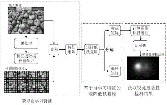
[0051] Such as figure 1 As shown, a visual saliency detection method based on self-learning features and matrix low-rank restoration is used in the implementation of the hardware environment: Intel(R)Core(TM)i5CPU 3.2G computer, 8GB memory, 1GB video memory card, running The software environment is: Matlab R2014b and Windows 7. The original image selected in the experiment is a color picture with a resolution of 681*511, such as figure 1 Shown in the upper left. Such as figure 1 As shown, the specific implementation steps of the present invention are as follows:
[0052] 1. Acquire self-learning features:
[0053] 1. Pretreatment:
[0054] 1) Image scaling: the original image with the size of k×g is scaled equally, the scaling ratio is a, and the scaled image size is ak×ag. Among them, k and g are non-negative integers, 0 <1, ak=round(k×a), ag=round(k×g), round(·) represents rounding operation.
[0055] In order to avoid too long calculation time of the method, which affects the operating efficiency, before the feature template self-learning, the image must be zoomed first to reduce the size of the image. Such as figure 1 As shown, the RGB color image (which has been processed in black and white) shown in the upper left part, the original image resolution is: 681×511, the zoom ratio selected in the experiment is 0.14, and the zoomed image resolution is 95×72.
[0056] 2) Image block: from the upper left corner to the lower right corner of the zoomed image, a b×b sliding window is used to sequentially intercept b×b image blocks, and each image block is between adjacent image blocks in the horizontal and vertical directions There is a 50% area overlap, and a 25% area overlap with adjacent image blocks in the ±45° direction; all intercepted image blocks are converted into column vectors, and combined into an image block vector matrix in the order of interception, Mark as: X = [x 1 ,x 2 ,...x N ]∈C m×N; Among them, C represents the set of natural numbers, x i ,i∈[1,N] represents the column vector corresponding to the i-th image block, and N is the image block x i The number of; m is the image block x i The dimension of, m=b×b×c, c is the number of image channels, b≥4, and b must be an even number. For example: if the input image is an RGB color image, then c=3; if it is a grayscale image, then c=1.
[0057] An 8×8 sliding window is used to overlap and block the zoomed image. Use an 8×8 sliding window to slide from the upper left corner of the image to the lower right corner: starting from the leftmost side of the first row, the sliding window slides 4 pixels to the right at a time, and the sliding window gets a window every time it goes The 8×8 color image block of the area, the width of the scaled image is 95 pixels, 95/4-1=22.75, after acquiring 22 image blocks, there are 3 pixels left in the first row, so the first row only lasts Moving 3 pixels, a total of 23 8×8 color image blocks are acquired in the first row. Move the sliding window down by 4 pixels, and start sliding the second row from the leftmost side of the image, using the same method as the first row, and so on, until you reach the lower right corner of the image. The height of the zoomed image is 72 pixels, 72/4-1=17, and the sliding window captures a total of 17 lines of image blocks, 23×17=391, that is, a total of 391 8×8 color image blocks are obtained. Since only 4 pixels are moved in the horizontal and vertical directions at a time, any image block overlaps 50% of the adjacent image blocks in the horizontal and vertical directions, and it overlaps the adjacent image blocks in the ±45° direction. There is 25% overlap between them.
[0058] Divide each 8×8 color image block x i Converted into a column vector. Each color image block includes three channels of R, G, and B. Each channel can be transformed into a 8×8=64-dimensional column vector, and three 64-dimensional column vectors are spliced ​​in the order of R, G, and B. Into a 64×3=192-dimensional column vector.
[0059] All image blocks x i The converted column vectors are spliced ​​to obtain an image block vector matrix. Image block x i The converted column vector is combined into an image block vector matrix in the order from the upper left corner to the lower right corner of the image, marked as X=[x 1 ,x 2 ,...x 391 ]∈C 192×391. Among them, C represents the set of natural numbers, x i ∈R 192 ,i ∈ [1,391] represents the column vector corresponding to the i-th image block (subsequently with x i Directly represents the i-th image block).
[0060] 2. Self-learning feature extraction:
[0061] 1) Self-learning of feature extraction template:
[0062] Taking the image block vector matrix X obtained after the previous image overlap and block division as the training sample set, then the adaptive feature extraction template W=[w 1 ,w 2 ,...w n ]∈R 192×n It can be obtained by solving the following objective function minimization problem:
[0063]
[0064] Among them, n represents the number of basis vectors in the feature extraction template W, which is set to 300; ||·|| 1 And ||·|| 2 Represents 1 norm and 2 norm operations respectively, α i It is an intermediate variable in the calculation process. Its initial value is set by a random number. 0.1 is a compromise parameter between the balance error (the first term of equation (1)) and the sparsity (the second term of equation (1)). Equation 1 is solved by the mexTrainDL function in SPArse Modeling Software (http://spams-devel.gforge.inria.fr/downloads.html).
[0065] 2) Obtain the self-learning feature matrix:
[0066] After the feature extraction template W is determined, any image block x i Eigenvector f i You can calculate the image block x i And the convolution of the basis vectors in the feature extraction template W to obtain:
[0067] f i = X i **W (2)
[0068] Among them, ** represents convolution operation, f i ∈R 300 ,i∈[1,391]. The feature vectors corresponding to all image blocks jointly form a feature matrix, namely: F=[f 1 ,f 2...,f 391 ]∈R 300×391. F is figure 1 The self-learning feature matrix of the input image.
[0069] 2. Matrix low-rank restoration based on self-learning features:
[0070] Using sparsity, the self-learning feature matrix F obtained in the previous step can be expressed as:
[0071] F=L+S (3)
[0072] In the above formula, L represents a low-rank matrix and S represents a sparse matrix, which can be expressed as:
[0073] L=[l 1 ,l 2 ,...l 391 ]∈R 300×391 (4)
[0074] S=[s 1 ,s 2 ,...s 391 ]∈R 300×391 (5)
[0075] Where l 1 ,l 2 ,...l 391 Represents the column of the low-rank matrix L, its length is 300, s 1 ,s 2 ,...s 391 Represents the column of the sparse matrix S, and its length is 300. For the input image, L represents the background area with strong feature correlation, and S represents the salient area of ​​the image. The low-rank matrix L and the sparse matrix S can be solved by matrix low-rank restoration, that is, the following objective function minimization problem can be solved:
[0076]
[0077] Among them, L * ∈R 300×391 And S * ∈R 300×391 Are the solution results of the low-rank matrix L and the sparse matrix S respectively, ||·|| * Represents nuclear norm operation, ||·|| 1 Represents 1 norm operation. Formula (6) can be solved by ALM (Augmented Lagrange Multiplier) algorithm (Zhouchen Lin, Minming Chen, and Yi Ma. The augmented lagrange multiplier method for exact recovery of corrupted low-rankmatrices. arXiv preprint arXiv: 1009.5055, 2010.).
[0078] 3. Obtain visual saliency test results:
[0079] 1. Calculate the visual saliency of any pixel:
[0080] 1) Obtain the visual saliency of any image block. In the previous step, the solved sparse matrix S is obtained * After that, calculate the solved sparse matrix S * The 1 norm of each column is the image block x i The visual saliency of:
[0081]
[0082] among them, i∈[1,391] represents the sparse matrix S * The i-th column, sr i ,i∈[1,N] represents the image block x corresponding to this column i Significant value of, ||·|| 1 Represents 1 norm operation.
[0083] 2) Obtain the visual saliency of any pixel. Since there is a 50% overlap between adjacent image blocks when the image is divided into blocks, the same pixel will be included in multiple image blocks. Therefore, the saliency value of any pixel must be calculated by calculating the saliency of all image blocks containing the pixel. The values ​​are worth:
[0084]
[0085] Among them, sr (x,y) Represents the saliency value of the pixel with coordinates (x, y). l represents the number of image blocks containing pixels (x, y). If the image block is located at the four vertices of the image, then l=3; if the image block is located at the boundary of the image except the four vertices, then l =5, in other positions, l=8. sr j ,j∈[1,l] represents the saliency value of the j-th image block containing pixel (x, y).
[0086] After finding the saliency value of all pixels in the image, use sr (x,y) As the gray value of the pixel at (x, y), the preliminary visual saliency image SM'∈R is obtained 95×72.
[0087] 2. Post-processing:
[0088] In order to obtain a better detection effect, it is necessary to perform Gaussian blur on the visually saliency image SM' obtained in the previous step:
[0089] SM gm =SM'**gm (9)
[0090] Among them, gm stands for Gaussian template, SM gm ∈R 95×72 Represents the blurred image. The standard deviation σ of the Gaussian kernel used by the Gaussian template gm is 0.03 times the image width, that is: σ=0.03×95=2.85; the Gaussian template gm is a square, and its side length d is about 4 times the standard deviation, that is: d= 2.85×4=11.4≈11, the principle of approximation is: select the closest odd number.
[0091] SM of the blurred image g Scale back to the original size of the input image 681×511, and round the gray values ​​of all pixels to get the final visually saliency image SM∈C 95×72 ,Such as figure 1 As shown in the lower right corner, the picture is figure 1 Enter the visual saliency detection result of the image in the upper left corner.
[0092] Experiments show that the method of the present invention can obtain a saliency detection accuracy rate of 91.29%, which is better than other similar saliency detection methods. Among them, the correct rate of saliency detection is defined as the ratio of the size of the saliency area correctly detected to the size of the total saliency area.
[0093] The above descriptions are only preferred embodiments of the present invention and are not intended to limit the present invention. Any modification, equivalent replacement, improvement, etc. made within the spirit and principle of the present invention shall be included in the present invention. Within the scope of protection.

PUM

no PUM

Description & Claims & Application Information

We can also present the details of the Description, Claims and Application information to help users get a comprehensive understanding of the technical details of the patent, such as background art, summary of invention, brief description of drawings, description of embodiments, and other original content. On the other hand, users can also determine the specific scope of protection of the technology through the list of claims; as well as understand the changes in the life cycle of the technology with the presentation of the patent timeline. Login to view more.

Similar technology patents

Maximum supply capacity evaluation method of distribution networks based on mixed integer linear programming

ActiveCN109066654Aavoid redundancyReduce the difficulty of quick solve
Owner:SHENZHEN POWER SUPPLY BUREAU +1

Intelligent gas cylinder with radio frequency identification tag

ActiveCN105354609Aavoid redundancyImprove the level of safety and security
Owner:上海炘璞电子科技有限公司

Snow melting and deicing system for light energy pavement

InactiveCN109338845Asave electricityavoid redundancy
Owner:中宇智慧光能科技有限公司

Large file storage system and large file processing method

InactiveCN111142780Aavoid redundancySimple structure
Owner:SHENZHEN IPANEL TECH LTD

Systrace information capturing method and device, storage medium and terminal

PendingCN110489318Areduce data volumeavoid redundancy
Owner:OPPO CHONGQING INTELLIGENT TECH CO LTD

Classification and recommendation of technical efficacy words

  • avoid redundancy

Data processing method, device and system

InactiveCN103294702Aavoid redundancyavoid wasting
Owner:上海淼云文化传播有限公司

Intelligent gas cylinder with radio frequency identification tag

ActiveCN105354609Aavoid redundancyImprove the level of safety and security
Owner:上海炘璞电子科技有限公司

Maximum supply capacity evaluation method of distribution networks based on mixed integer linear programming

ActiveCN109066654Aavoid redundancyReduce the difficulty of quick solve
Owner:SHENZHEN POWER SUPPLY BUREAU +1

Snow melting and deicing system for light energy pavement

InactiveCN109338845Asave electricityavoid redundancy
Owner:中宇智慧光能科技有限公司

Large file storage system and large file processing method

InactiveCN111142780Aavoid redundancySimple structure
Owner:SHENZHEN IPANEL TECH LTD
Why Eureka
Try Eureka