Cable wrapping machine

A technology of cable wire and wrapping machine, which is applied in the direction of cable/conductor manufacturing, conductor/cable insulation, circuit, etc. It can solve the problems of tape scrapping, welding difficulties, easily damaged tape reels and conductors, etc. good quality cable

Active Publication Date: 2017-02-22
SHANDONG KUNYU CABLE
View PDF5 Cites 23 Cited by
  • Summary
  • Abstract
  • Description
  • Claims
  • Application Information

AI Technical Summary

Problems solved by technology

[0003] The main defects of the cable wrapping machine that fixes the tape tray on the upper part of the introduction tube are: (1) The tape tray is very thin (5-10MM); the circumference is large (260-300MM) and it is easy to break, once broken The entire tape is scrapped. It is difficult to remove the waste disk and replace it with a new disk. It is often necessary to cut off the cable core.
When producing multi-strand flexible wires, after the core is cut off, welding is difficult. After welding, there are hard spots and uneven welding of multiple strands, which seriously affects product quality.
(2) When double-layer wrapping is required, the cable core must be worn twice on the tape core, and if it is cut off, it is easy to damage the tape reel and conductor during the welding operation

Method used


Image

  • Cable wrapping machine
  • Cable wrapping machine
  • Cable wrapping machine

Examples


Embodiment Construction

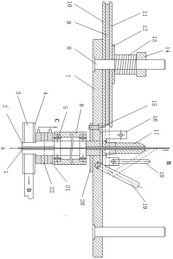
[0018] The cable wrapping machine of the present invention comprises a frame, a wire-releasing guide wheel and a wire-receiving guide wheel, and the structures of the frame, the wire-releasing guide wheel and the wire-receiving guide wheel are prior art, and there is no schematic diagram in the figure. Main shaft 2 is fixed with support 6 through bearing 5, and support 6 is fixed on the frame.

[0019] The cable core wire 1 enters from the direction indicated by A, and enters the take-up guide wheel from the direction indicated by B.

[0020] The cable lead-in pipe 17 is vertically arranged on the frame, the cable lead-in pipe 17 is coaxially arranged with the main shaft 2, the main shaft 2 is connected with the transmission wheel 4, and the driving motor drives the transmission wheel 4 through the belt 3, thereby driving the main shaft 2 to rotate. The main shaft 2 is provided with a mounting seat 20, which rotates together with the main shaft 2, and the two sides of the moun...


PUM


Abstract

The invention discloses a cable wrapping machine. The cable wrapping machine comprises a frame, a pay-off guide wheel and a take-up guide wheel. A vertical cable guide tube is arranged on the frame and in coaxial arrangement with a spindle, and a mounting seat is arranged on the spindle which is driven to rotate by a motor. Rotating plates are symmetrically fixed to two sides of the mounting seat, a wrapping belt mounting vertical shaft is vertically arranged on each rotating plate, and a wrapping belt lower tray, a wrapping belt and a wrapping belt upper tray sequentially sleeves each mounting vertical shaft. Two groups of belt guide shafts are arranged on the mounting seat; the first group of the belt guide shafts is arranged on the outer side of the cable guide tube, and an included angle between first belt guide shafts and the cable guide tube is adjustable in a range of 0-180 degrees; the second group of the belt guide shafts is arranged close to the rotating plates, and an included angle between second belt guide shafts and the cable guide tube is adjustable in a range of 0-90 degrees; each rotating plate corresponds to one of the first belt guide shafts and one of the second belt guide shafts. The cable wrapping machine has advantages that replacement of wrapping belts can be realized without cutting of cores when the wrapping belts are used up, convenience in replacement is realized, core wires are unaffected, and produced cables are high in quality.

Description

technical field [0001] The invention belongs to the technical field of cable production equipment, and relates to a cable wrapping machine. Background technique [0002] In the cable production process, insulating ribbon or insulating film needs to be wrapped around the exposed wire or cable core. For example, mica tape is wrapped around the core wire of the cable, which plays the role of insulation and fire resistance, and enhances the safety of the cable. In the prior art, the core wire of the cable is passed through the center hole of the taping reel to wrap the wrapping method. When the tape is used up, the core wire of the cable must be cut off before a new tape reel can be replaced. In order to provide sufficient tape for the cable, the solution is to pre-load multiple tape reels according to the length of the cable core wire to be wrapped before inserting the cable core wire, and cut off the reel manually with a knife after one reel is used up. Core, then replace th...

Claims


Application Information

Patent Timeline
Patent Type & Authority Applications(China)
IPC IPC(8): H01B13/10H01B13/26
CPCH01B13/10H01B13/2613
Inventor 孙文斌杨庆贵刘芳香
Owner SHANDONG KUNYU CABLE
Why Eureka
Try Eureka