Iron core structure of reel iron core transformer
A technology of iron core structure and wound iron core, applied in the direction of transformer/inductor magnetic core, transformer/inductor components, transformer/inductor cooling, etc., can solve problems such as unsatisfactory heat dissipation and complex structure, and reduce manufacturing Difficulty and manufacturing cost, effect of reducing temperature rise
- Summary
- Abstract
- Description
- Claims
- Application Information
AI Technical Summary
Problems solved by technology
Method used
Image

Examples
Embodiment 1
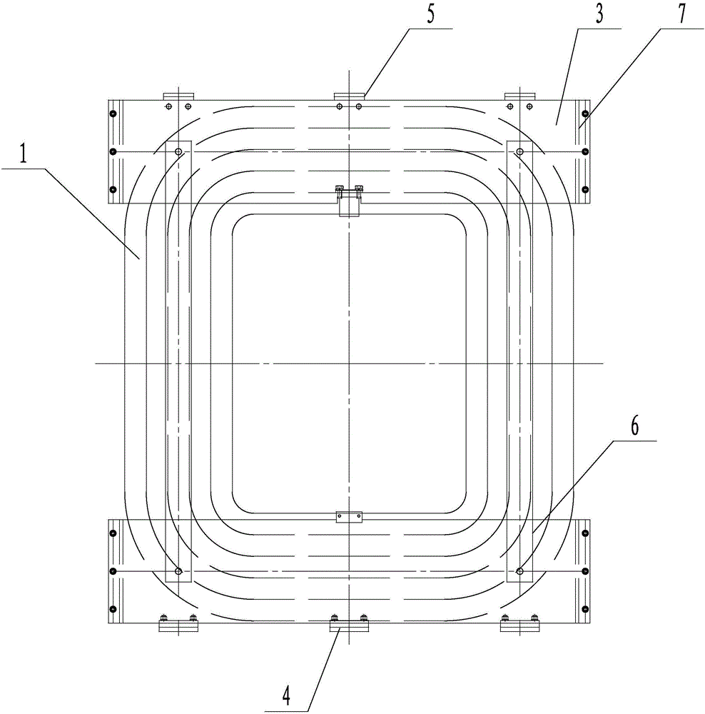
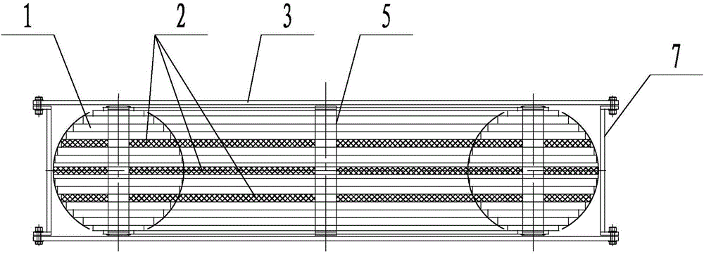
[0025] Such as Figure 1-3 As shown, an iron core structure of a wound core transformer includes an iron core body formed by stacking multi-layer closed wound iron core laminations 1, and an iron core oil channel 203 arranged in the iron core body. In the stacking direction, the iron core body is divided into core splits that do not touch each other through several iron core oil passage layers 2 to replace the closed-rolled iron core laminations 1 of the layer, and each iron core split is It consists of several stacked closed-roll iron core laminations 1, and each core oil passage layer 2 is composed of several adjacent iron core oil passages 203 on the same level.
Embodiment 2
[0027] In order to realize the arrangement of an odd number of iron core oil passage layers 2 on the rolled iron core to achieve a more optimized heat dissipation effect, the following is an example where three iron core oil passage layers 2 replace the closed wound iron core lamination 1 of the layer:
[0028] Such as figure 1 , 2 , 4, and 5, the iron core body is divided into four non-contacting core bodies by replacing the closed-rolled iron core laminations 1 of the layer with three iron core oil channel layers 2 in the stacking direction. The iron core is separated, and one of the iron core oil passage layers 2 replaces the closed-rolled iron core lamination 1 located in the center layer of the iron core. The four iron core splits and the remaining two iron core oil passage layers 2 are symmetrical Distributed on both sides of the central iron core oil channel layer 2, the two outer iron core splits are formed by stacking five closed coil iron core laminations 1, because...
Embodiment 3
[0042] In order to achieve an even number of iron core oil passage layers 2 arranged on the wound iron core to achieve a more optimized heat dissipation effect, the following is an example where two iron core oil passage layers 2 replace the closed wound iron core lamination 1 of the layer, and The difference between the two examples above is:
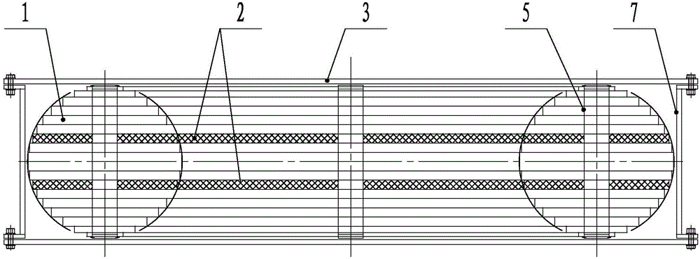
[0043] Such as figure 1 , 2 As shown, the iron core is divided into three separate iron cores that do not touch each other through two iron core oil passage layers 2 in the stacking direction instead of the closed coiled iron core laminations 1 of the layer. , the three iron core splits and two iron core oil passage layers 2 are symmetrically distributed on both sides of the center plane of the iron core body. Since the heat in the middle part of the iron core is higher, better heat dissipation is required. The two iron cores The thickness of the split body of the iron core between the core oil passage layers 2 is smaller than the th...
PUM
 Abstract
Description
Claims
Application Information
 - R&D
- Intellectual Property
- Life Sciences
- Materials
- Tech Scout
- Unparalleled Data Quality
- Higher Quality Content
- 60% Fewer Hallucinations
Browse by: Latest US Patents, China's latest patents, Technical Efficacy Thesaurus, Application Domain, Technology Topic, Popular Technical Reports.
© 2025 PatSnap. All rights reserved.Legal|Privacy policy|Modern Slavery Act Transparency Statement|Sitemap|About US| Contact US: help@patsnap.com