
Printing type top-emitting electroluminescent display and preparation method thereof

A top-emission and electroluminescence technology, which is used in the manufacture of electric solid-state devices, semiconductor/solid-state devices, circuits, etc., can solve the problems of poor display brightness uniformity and luminous interference, and achieve good brightness uniformity and display effect. The effect of improving electrical conductivity and improving brightness unevenness

Active Publication Date: 2017-02-22
武汉国创科光电装备有限公司
View PDF5 Cites 23 Cited by
  • Summary
  • Abstract
  • Description
  • Claims
  • Application Information

AI Technical Summary

Problems solved by technology

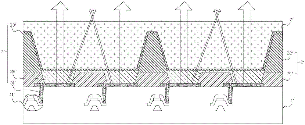
[0005] The purpose of the present invention is to provide a printed top-emission electroluminescent display and its preparation method, aiming to solve the problem of serious luminous interference between sub-pixels of the same color connected to the existing printed top-emission electroluminescent display, and the The problem that the display brightness uniformity of the display is deteriorated due to the thin transparent electrode

Method used


Image

  • Printing type top-emitting electroluminescent display and preparation method thereof
  • Printing type top-emitting electroluminescent display and preparation method thereof
  • Printing type top-emitting electroluminescent display and preparation method thereof

Examples


Embodiment Construction

[0030] In order to make the technical problems, technical solutions and beneficial effects to be solved by the present invention clearer, the present invention will be further described in detail below with reference to the embodiments. It should be understood that the specific embodiments described herein are only used to explain the present invention, but not to limit the present invention.

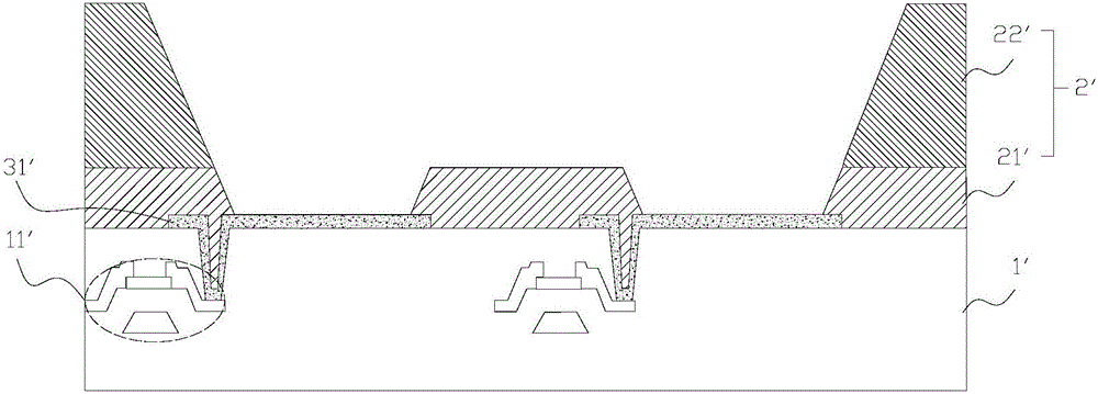
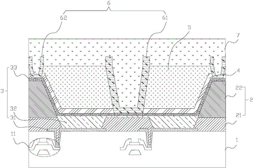
[0031] combine image 3 , 4 , an embodiment of the present invention provides a printed top emission electroluminescent display, comprising:

[0032] TFT array substrate 1;

[0033] A pixel bank (pixel defining layer) 2 disposed on the TFT array substrate 1, wherein the pixel bank 2 includes a first pixel defining layer disposed on the TFT array substrate 1 for defining a sub-pixel light-emitting region 21, and a second pixel defining layer 22 disposed on the first pixel defining layer 21 for defining adjacent sub-pixels of the same color;

[0034] The light-emitting element 3 dispo...


PUM


Abstract

The invention provides a printing type top-emitting electroluminescent display. The printing type top-emitting electroluminescent display comprises a TFT array substrate, a pixel bank, a light-emitting component, an auxiliary electrode, a first thin film packaging layer, a filling layer and a second thin film packaging layer, wherein the pixel bank is arranged on the TFT array substrate; the pixel bank comprises a first pixel defining layer and a second pixel defining layer; the first pixel defining layer is arranged on the TFT array substrate and is used for defining a sub-pixel light-emitting area; the second pixel defining layer is arranged on the first pixel defining layer and is used for defining connected sub-pixels with the same color; the light-emitting component is arranged in the sub-pixel light-emitting area; the light-emitting component comprises an imagination pixel electrode, a functional layer and a transparent top electrode which are arranged on the TFT array substrate sequentially; the imagination pixel electrode is electrically connected with a TFT array; the transparent top electrode extends to cover the pixel bank; the auxiliary electrode is arranged on the transparent top electrode on the pixel bank and is connected with the transparent top electrode; the first thin film packaging layer and the filling layer are arranged on the transparent top electrode without the auxiliary electrode sequentially; and the second thin film packaging layer covers the auxiliary electrode and the filling layer.

Description

technical field [0001] The invention belongs to the technical field of display, and in particular relates to a printed top emission electroluminescence display and a preparation method thereof. Background technique [0002] In the contemporary age of the information society, the importance of display devices as a visual information transmission medium is further strengthened. In order to dominate in the future, display devices are moving towards lighter, thinner, lower power consumption, lower cost and better Trends in image quality. [0003] Because organic electroluminescent diodes (OLEDs) have the advantages of self-luminescence, fast response, wide viewing angle, high brightness, and lightness, etc., while quantum dot light-emitting diodes (QLEDs) have the advantages of high light color purity, high light-emitting quantum efficiency, easy-to-adjust light-emitting color, Due to the advantages of long service life, OLED and QLED have become the two main directions of curr...

Claims


Application Information

Patent Timeline
Patent Type & Authority Applications(China)
IPC IPC(8): H01L27/32H01L51/52H01L21/77
CPCH10K59/122H10K50/805H10K59/1201H10K2102/3026
Inventor 陈亚文
Owner 武汉国创科光电装备有限公司
Learn More