Battery pack air cooling system

An air-cooling system and battery pack technology, applied to secondary batteries, battery/fuel cell control devices, circuits, etc., can solve problems such as access, achieve heat dissipation balance, ensure charging and discharging, and good heat dissipation effects

Active Publication Date: 2017-02-22
湖南小步科技有限公司
View PDF17 Cites 6 Cited by
  • Summary
  • Abstract
  • Description
  • Claims
  • Application Information

AI Technical Summary

Problems solved by technology

[0004] The purpose of the present invention is to provide a battery pack air cooling system with simple structure and good heat dissipation effect, which can dissipate heat from the battery pack during the charging and discharging process of the power lithium battery, and the heat dissipation is relatively balanced; The technical problem that liquids such as moisture enter the battery pack, and the waterproof effect is good

Method used


Image

  • Battery pack air cooling system
  • Battery pack air cooling system
  • Battery pack air cooling system

Examples


Embodiment 1

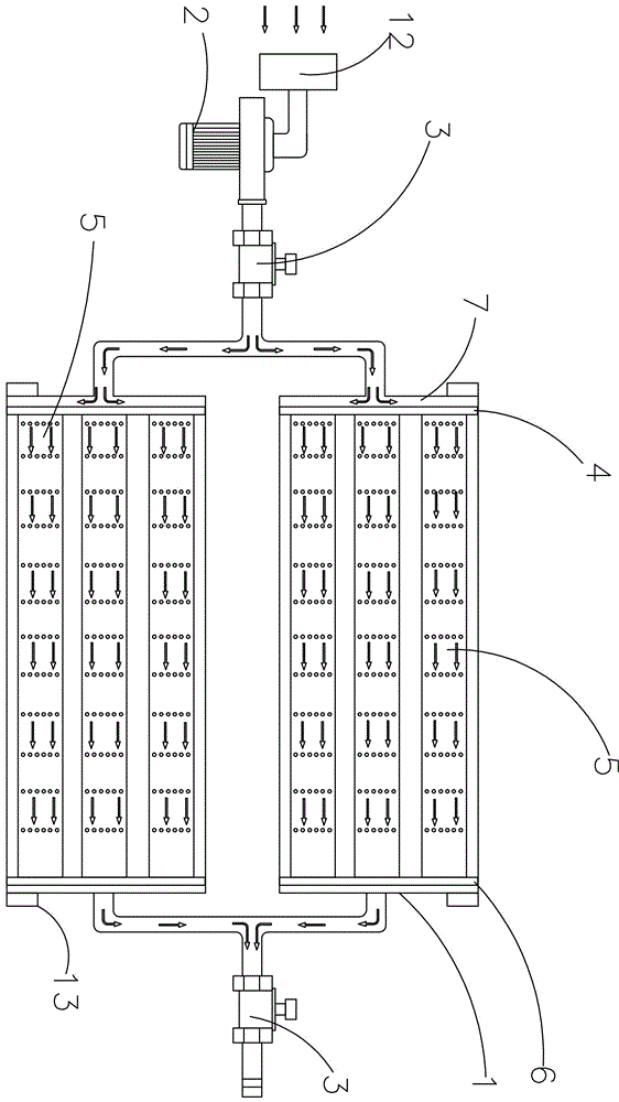
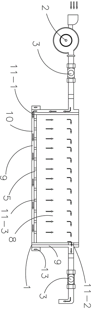
[0036] as attached figure 1 And attached figure 2 As shown, a battery pack air-cooling system includes a box body 1, a fan 2 located outside the box body 1 and connected to the inside of the box body through a draft tube, and a wind cover connected to the air inlet of the fan 2 through a downflow tube 12 and the waterproof device that is arranged on the casing 1 outside.

[0037] The first deflector 4 and the second deflector 6 are connected between the front and rear sides of the inner cavity of the box body 1, and the top of the first deflector 4 and the top of the second deflector 6 are connected to the top wall of the inner cavity of the box. , the bottom end of the first deflector 4 and the bottom end of the second deflector 6 are connected to the bottom wall of the box cavity, between the first deflector 4 and the second deflector 6 and close to the bottom of the box cavity Three third deflectors 5 are connected; the three third deflectors 5 are arranged in parallel b...

Embodiment 2

[0045] as attached figure 1 And attached figure 2 As shown, a battery pack air-cooling system includes a box body 1, a fan 2 located outside the box body 1 and connected to the inside of the box body through a draft tube, and a wind cover connected to the air inlet of the fan 2 through a downflow tube 12 and the waterproof device that is arranged on the casing 1 outside.

[0046] The first deflector 4 and the second deflector 6 are connected between the front and rear sides of the inner cavity of the box body 1, and the top of the first deflector 4 and the top of the second deflector 6 are connected to the top wall of the inner cavity of the box. , the bottom end of the first deflector 4 and the bottom end of the second deflector 6 are connected to the bottom wall of the box cavity, between the first deflector 4 and the second deflector 6 and close to the bottom of the box cavity Three third deflectors 5 are connected; the three third deflectors 5 are arranged in parallel b...


PUM


Abstract

The invention provides a battery pack air cooling system. The battery pack air cooling system comprises a box body and a fan which is disposed outside the box body and communicated with the interior of the box body by virtue of a guide pipe, wherein an inner cavity of the box body is divided by a first guide plate, a second guide plate and a third guide plate which are arranged in the inner cavity of the box body into a first guide air duct, a battery assembling cavity, a second guide air duct and a third guide air duct, the first guide air duct is communicated with the third guide air duct by virtue of a first guide hole formed at a position adjacent to the bottom end of the first guide plate, the third guide air duct is communicated with the battery assembling cavity by virtue of a third guide hole formed in the third guide plate, and the battery assembling cavity is communicated with the second guide plate by virtue of a second guide hole formed in the second guide plate; and an air outlet of the fan is communicated with the first guide air duct by virtue of the guide pipe, and the second guide air duct is communicated with the exterior by virtue of the guide pipe. The battery pack air cooling system can perform heat dissipation and water resistance for a battery pack, and is relatively homogenous in heat dissipation, simple in structure, and good in heat dissipation effect.

Description

technical field [0001] The invention relates to the technical field of electric vehicle electronic circuits, in particular to a battery pack air cooling system. Background technique [0002] As the energy supply source for electric devices in large-scale equipment such as electric vehicles, motorcycles, and motor boats, during the charging and discharging process of power lithium batteries, the internal chemical side reactions and internal resistance of the battery will generate a lot of heat. In the environment, its charging and discharging performance and working life will be greatly reduced, and it will bring safety hazards to the battery pack. In order to allow the single cells in the battery pack to work within the normal temperature range, the battery pack is generally designed with a heat dissipation system. At present, the air-cooled heat dissipation system used in the power lithium battery pack of domestic electric vehicles generally suffers from poor heat dissipati...

Claims


Application Information

Patent Timeline
Patent Type & Authority Applications(China)
IPC IPC(8): H01M10/613H01M10/625H01M10/0525H01M10/6563B60L11/18
CPCH01M10/0525H01M10/613H01M10/625H01M10/6563B60L58/26Y02E60/10Y02T10/70
Inventor 李勇刘广曾祥华
Owner 湖南小步科技有限公司
Why Eureka
Try Eureka