Multi-rotor motor

A multi-rotor and rotor technology, applied in the field of aircraft, can solve problems such as motor overheating, motor failure, and propulsion system failure, and achieve the effects of reducing the probability of failure, improving heat dissipation, and avoiding the wrong installation of positive and negative propellers

Pending Publication Date: 2017-02-22
SHANGHAI XPARTNER ROBOTICS
View PDF0 Cites 0 Cited by
  • Summary
  • Abstract
  • Description
  • Claims
  • Application Information

AI Technical Summary

Problems solved by technology

Through the test, it is found that frequent starting or long-term load operation of the motor will cause the motor to overheat, and overheating may cause the motor to fail, resulting in the failure of the propulsion system
[0003] At present, there is no good solution for the heat dissipation of multi-rotor motors. Digging grooves or holes on the rotor can achieve a certain effect.

Method used


Image

  • Multi-rotor motor
  • Multi-rotor motor
  • Multi-rotor motor

Examples


Embodiment Construction

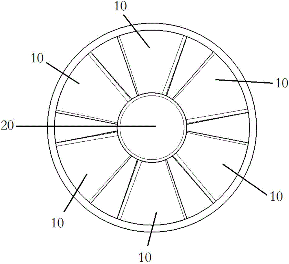
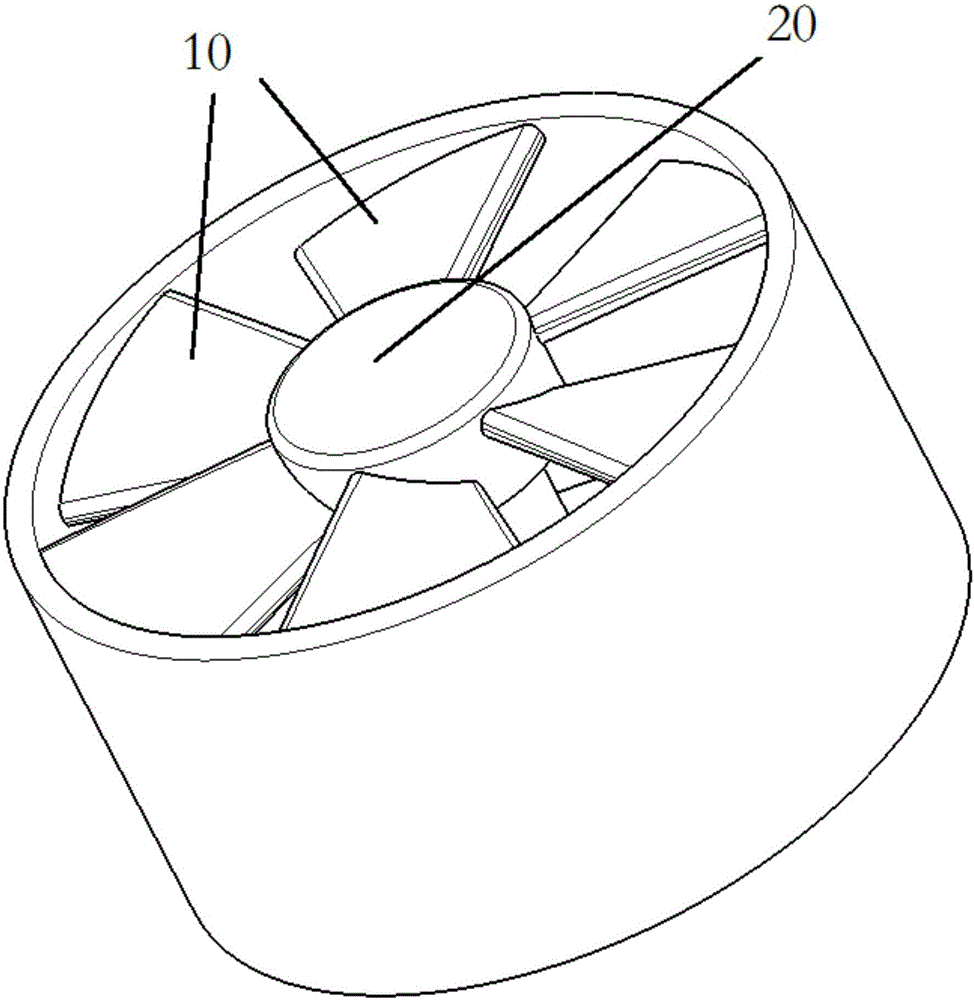
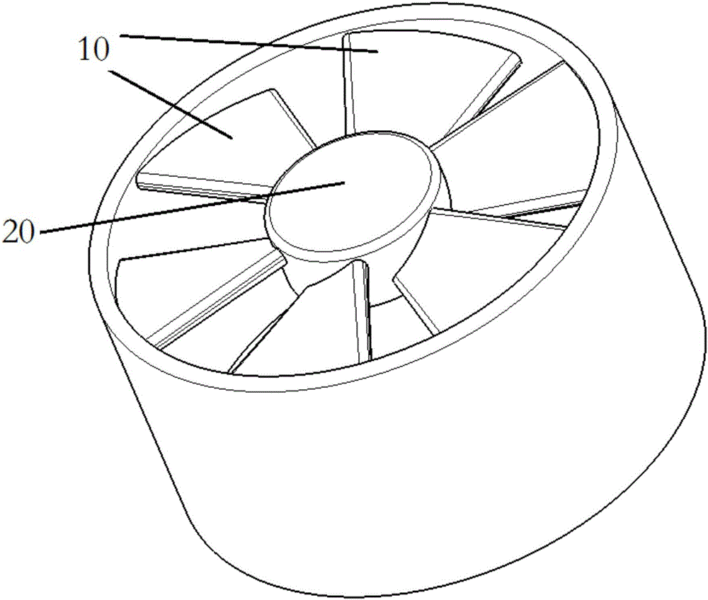
[0021] figure 1 is a schematic top view of a multi-rotor motor according to a preferred embodiment of the present invention. figure 2 It is an axial perspective schematic diagram of a multi-rotor motor rotating in the forward direction according to a preferred embodiment of the present invention. image 3 It is an axial perspective schematic diagram of a counter-rotating multi-rotor motor according to a preferred embodiment of the present invention. Figure 4 is a motor sectional view of a multi-rotor motor according to a preferred embodiment of the present invention.

[0022] like figure 1 , figure 2 , image 3 and Figure 4 As shown, the multi-rotor motor according to the preferred embodiment of the present invention includes: a plurality of fan-shaped blades 10 formed on the top of the external rotor of the motor, wherein the root of each fan-shaped blade 10 is fixedly connected to the rotor shaft 20 of the multi-rotor motor, each The tip of the fan-shaped blade 10 ...


PUM


Abstract

The invention discloses a multi-rotor motor. The multi-rotor motor comprises multiple fan vanes formed on the top of an external rotor of the motor. The root of each fan vane is fixedly connected to a rotor shaft of the multi-rotor motor, and the tip of each fan vane is fixedly connected to a rotor shell of the multi-rotor motor. Under the condition of the multi-rotor motor and blades, the multiple fan vanes are located at the end of the multi-rotor motor near the blades.

Description

technical field [0001] The invention relates to the field of aircraft and the field of motors, in particular to a multi-rotor motor. Background technique [0002] At present, with the continuous improvement of technology, multi-rotor aircraft has been applied in more and more fields. As a multi-rotor propulsion system, the working reliability of electric motors and blades is extremely important. Through tests, it is found that frequent starting or long-term load operation of the motor will cause the motor to overheat, and overheating may cause the motor to fail, thereby leading to the failure of the propulsion system. [0003] At present, there is no good solution for the heat dissipation of multi-rotor motors. Digging grooves or holes on the rotor can achieve a certain effect. At the same time, check before the test flight or listen to the sound of the motor to judge whether the motor is damaged. [0004] Therefore, those skilled in the art are devoting themselves to deve...

Claims


Application Information

Patent Timeline
Patent Type & Authority Applications(China)
IPC IPC(8): H02K9/06
CPCH02K9/06
Inventor 恽为民张栋梁庞作伟
Owner SHANGHAI XPARTNER ROBOTICS
Why Eureka
Try Eureka