Spatially phase-modulated annular traveling wave ultrasonic motor with symmetrical ceramic partitions and its control method

A ceramic and space technology, which is applied in the field of space phase modulation annular traveling wave ultrasonic motor and its control, can solve the problems of reduced silver-coated area, complicated motor wiring, difficult ceramic processing, etc., and achieves the effect of simplified wiring

Active Publication Date: 2019-05-07
NANJING INST OF TECH
View PDF6 Cites 0 Cited by
  • Summary
  • Abstract
  • Description
  • Claims
  • Application Information

AI Technical Summary

Problems solved by technology

[0003] At present, the piezoelectric ceramics of the traditional space-modulated annular traveling wave ultrasonic motor adopts a subdivided ceramic structure, and each ceramic partition is half of that of the traditional annular traveling wave ultrasonic motor, and the number of partitions is doubled, which will cause the following problems: 1. The total area of ​​the insulation between the partitions increases, resulting in a decrease in the silver-covered area and a decrease in the power of the motor; 2. The partitions of the phases are separated from each other, resulting in complicated and difficult wiring of the motor; 3. The reduction in the area of ​​the ceramic partitions leads to a decrease in the ceramic processing Difficult and does not contribute to the improvement of ceramic machining accuracy

Method used


Image

  • Spatially phase-modulated annular traveling wave ultrasonic motor with symmetrical ceramic partitions and its control method
  • Spatially phase-modulated annular traveling wave ultrasonic motor with symmetrical ceramic partitions and its control method
  • Spatially phase-modulated annular traveling wave ultrasonic motor with symmetrical ceramic partitions and its control method

Examples


Embodiment

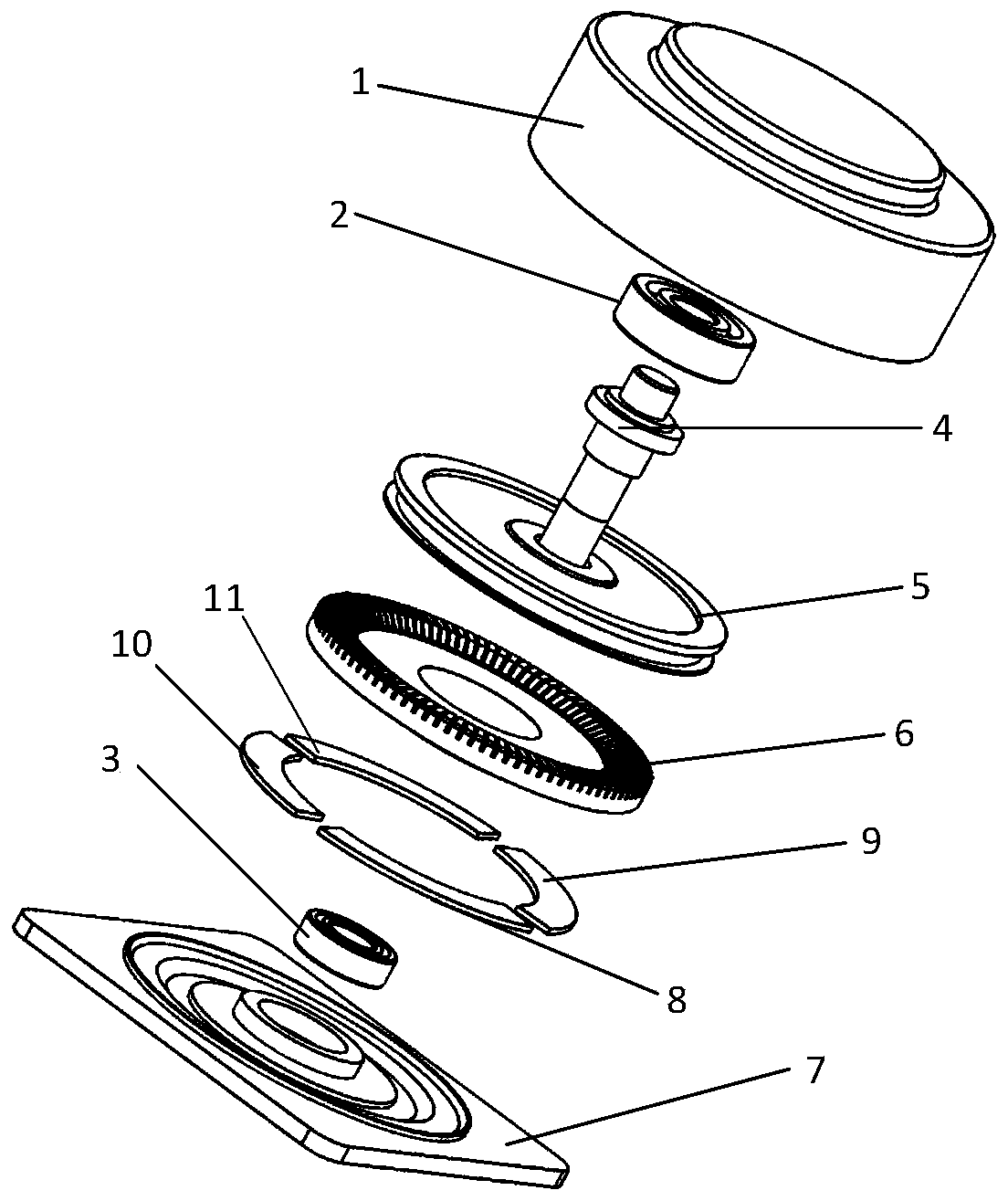
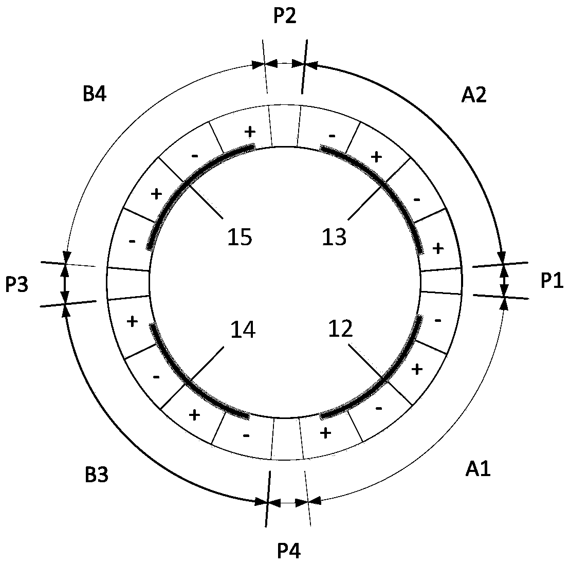
[0020] Such as figure 1 As shown, a spatial phase-modulated annular traveling wave ultrasonic motor with symmetrical ceramic partitions includes an end cover 1, a bearing 1 2, a bearing 2 3, a rotating shaft 4, a rotor 5, a stator 6, a base 7 and piezoelectric ceramics. Except for the zoning and polarization zoning methods of piezoelectric ceramics, the other structures, materials and assembly schemes of the motor are completely consistent with the traditional annular traveling wave ultrasonic motor. The piezoelectric ceramics of the spatially modulated annular traveling wave ultrasonic motor with symmetrical ceramic partitions in the embodiment are divided into piezoelectric ceramics 8 in A1 area, piezoelectric ceramics 9 in A2 area, piezoelectric ceramics 10 in area B3 and piezoelectric ceramics 11 in area B4. Such as figure 2 As shown, when the motor is working, space traveling waves with nine wavelengths are distributed on the circumference of the stator. If each traveli...


PUM


Abstract

The invention provides a spatial phase modulation round traveling wave ultrasonic motor with symmetrical ceramic zones and a control method of the ultrasonic motor. The ultrasonic motor comprises piezoelectric ceramics. The piezoelectric ceramics comprise A1-zone piezoelectric ceramics, A2-zone piezoelectric ceramics, B3-zone piezoelectric ceramics and B4-zone piezoelectric ceramics. All ceramic zones are arrayed according to the A1-zone piezoelectric ceramics, the A2-zone piezoelectric ceramics, the B4-zone piezoelectric ceramics and the B3-zone piezoelectric ceramics along the circumference in space and are separated from one another by a quarter of wavelength, and each ceramic zone takes up two wavelengths in space. The width of each polarized zone of the piezoelectric ceramics is one-half wavelength. According to the counter-clockwise direction, the polarized directions of all polarized zones of the piezoelectric ceramics are sequentially arrayed according to a positive and negative alternating sequence. The motor and the control method thereof have all the functions and advantages of a traditional spatial phase modulation round traveling wave ultrasonic motor with a subdivided ceramic structure, moreover, each polarized zone of the piezoelectric ceramics is wider, all polarized zones of each zone of piezoelectric ceramics keep continuous in space, and processing and manufacture are more convenient and accurate.

Description

technical field [0001] The invention relates to a space-phase-modulated annular traveling-wave ultrasonic motor with symmetrical ceramic partitions and a control method thereof. Background technique [0002] Space phase-modulated annular traveling wave ultrasonic motor is a kind of annular traveling wave ultrasonic motor which realizes spatial phase control through voltage regulation. The new control quantity of space phase provides more choices for the control of annular traveling wave motor. [0003] At present, the piezoelectric ceramics of the traditional space-modulated annular traveling wave ultrasonic motor adopts a subdivided ceramic structure, and each ceramic partition is half of that of the traditional annular traveling wave ultrasonic motor, and the number of partitions is doubled, which will cause the following problems: 1. The total area of ​​the insulation between the partitions increases, resulting in a decrease in the silver-covered area and a decrease in th...

Claims


Application Information

Patent Timeline
Patent Type & Authority Patents(China)
IPC IPC(8): H02N2/14H02N2/16
CPCH02N2/14H02N2/16
Inventor 郝思鹏胡霞陆旦宏蒋春容张津杨
Owner NANJING INST OF TECH
Why Eureka
Try Eureka