Bracket for driving multi-azimuth monitoring of camera

A multi-directional, camera technology, applied in the field of camera brackets, can solve problems such as increased cost, impact on monitoring quality, degree of monitoring angle image size, unfavorable camera control, etc., and achieves stable operation, stable movement, and reasonable structural design.

Inactive Publication Date: 2017-02-22
CHENGDU HANZHI INFORMATION TECH
View PDF0 Cites 7 Cited by
  • Summary
  • Abstract
  • Description
  • Claims
  • Application Information

AI Technical Summary

Problems solved by technology

Therefore, the monitoring bracket is an indispensable accessory product for using the camera. If the monitoring bracket cannot be better supported and moved, it is likely to affect its monitoring quality, monitoring angle, and the size of the obtained image.
The camera in the prior art can only be

Method used


Image

  • Bracket for driving multi-azimuth monitoring of camera
  • Bracket for driving multi-azimuth monitoring of camera
  • Bracket for driving multi-azimuth monitoring of camera

Examples


Embodiment 1

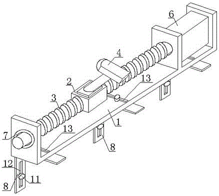
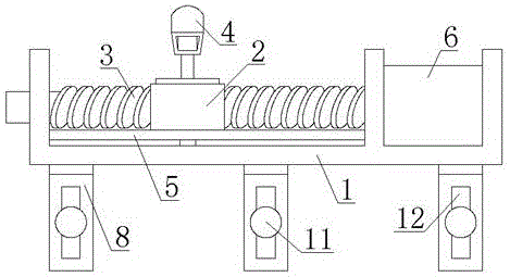
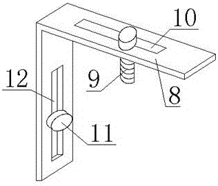
[0023] A support 1 for driving camera 4 multi-directional monitoring, such as Figure 1 to Figure 3 As shown, it includes a base 1 and a right-angle bracket 8 for fixing the base 1. The base 1 is provided with an adjustment groove 10, and the right-angle bracket 8 is provided with a b adjustment groove 13 adapted to the a adjustment groove 10, and The a adjustment groove 10 is connected with the b adjustment groove 13 through the a bolt 9, and a slide bar is provided on the base 1, and a mobile support 2 is sleeved on the slide bar, and a guide plate 5 is provided at the bottom of the mobile support 2 to guide The board 5 is installed on the base 1, and the camera 4 is installed on the mobile support 2.

[0024] During installation, first align the a adjustment groove 10 with the b adjustment groove 13, connect the base 1 with the right-angle bracket 8 through the cooperation of the a bolt 9 and the nut, and then install the right-angle bracket 8 on the wall. The base 1 is pr...

Embodiment 2

[0026] This embodiment is further optimized on the basis of the above embodiments, such as Figure 1 to Figure 3 As shown, further, the sliding rod is a screw rod 3, the moving support 2 is provided with an internal thread adapted to the screw rod 3, and the screw rod 3 and the moving support 2 are connected by threads. The sliding rod is set as the screw rod 3 and connected with the mobile support 2 through threads, so that the precise positioning of the camera 4 on the screw rod 3 can be realized.

Embodiment 3

[0028] This embodiment is further optimized on the basis of the above embodiments, such as Figure 1 to Figure 3 As shown, further, a drive motor 6 is provided on one side of the base 1 , and the output shaft of the drive motor 6 is connected to the screw rod 3 . The driving motor 6 can drive the screw to rotate, and can automatically control the movement of the camera 4 on the screw 3, thereby facilitating the operation of the operator.


PUM


Abstract

The invention discloses a bracket for driving multi-azimuth monitoring of a camera. The bracket comprises a base and a right-angled bracket for fixing the base, wherein an adjusting groove a is formed in the base, an adjusting groove b matched with the adjusting groove a is formed in the right-angled bracket, the adjusting groove a and the adjusting groove b are connected by a bolt a, a slide bar is arranged on the base, a moving support sleeves on the slide bar, a guide plate is arranged at the bottom of the moving support, the guide plate is installed on the base, the camera is installed on the moving support, the slide bar is a lead screw, the moving support is provided with internal threads matched with the lead screw, the lead screw is connected with the moving support through threads, a drive motor is arranged on one side of the base, and an output shaft of the drive motor is connected with the lead screw. The bracket disclosed by the invention has the beneficial effects that the camera can be driven to horizontally move to realize multi-angle monitoring of the camera; remote operation of an operator is facilitated; and the structural design is reasonable, and the camera stably runs.

Description

technical field [0001] The invention relates to the technical field of camera brackets, in particular to a bracket for driving cameras for multi-directional monitoring. Background technique [0002] Camera, also known as computer camera and electronic eye, is a video input device that is widely used in video conferencing, telemedicine and real-time monitoring. Ordinary people can also talk and communicate with each other with images and sounds on the Internet through the camera. The camera needs to be installed on the bracket to be better used. Therefore, the monitoring bracket is an indispensable accessory product for using the camera. If the monitoring bracket cannot be better supported and moved, it is likely to affect its monitoring quality, monitoring angle, and the size of the obtained image. The camera in the prior art can only be rotated at a fixed point to obtain a relatively large monitoring range, but if it is necessary to monitor multiple corners in an area, it ...

Claims


Application Information

Patent Timeline
IPC IPC(8): H04N7/18H04N5/232G03B17/56
CPCH04N7/183G03B17/561H04N23/60
Inventor 肖黎
Owner CHENGDU HANZHI INFORMATION TECH
Why Eureka
Try Eureka