System and method for automatic alignment and projection mapping

A projection and projector technology, applied in the field of projectors

Active Publication Date: 2017-02-22
CHRISTIE DIGITAL SYST USA INC
View PDF2 Cites 14 Cited by
  • Summary
  • Abstract
  • Description
  • Claims
  • Application Information

AI Technical Summary

Problems solved by technology

If the projector moves relative to the 3D object the image is being projected onto, the manual setup process / manual winding needs to be repeated, the technician visits the site again to perform the winding, which can lead to downtime for the projection system
While there are some automated systems that automatically perform warping on 3D objects, generally these systems only work for uncomplex geometries
Alternatively, the projector pose can be determined manually by a technician manually dragging points onto the object, an inverse calculation is used to determine where the projector is located, however this method suffers from the same problems as manual winding

Method used


Image

  • System and method for automatic alignment and projection mapping
  • System and method for automatic alignment and projection mapping
  • System and method for automatic alignment and projection mapping

Examples


Embodiment Construction

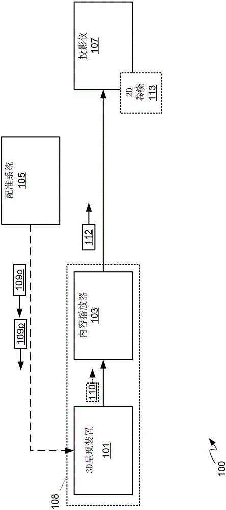
[0048] figure 1 A system 100 is shown comprising: a 3D (“three-dimensional”) rendering device 101 (hereinafter interchangeably referred to as device 101 ); a content player 103 ; a registration system 105 ; and a projector 107 . Typically, device 101 is in communication with content player 103 and registration system 105 , and content player 103 is in communication with projector 107 . As shown, device 101 and content player 103 are combined in one device 108, however, in other implementations device 101 and content player 103 are separate devices. The registration system is configured to generate pose data 109p including virtual position, virtual orientation, and virtual lens properties corresponding to the virtual camera of projector 107, and to transmit pose data 109p to device 101, as described in more detail below. Apparatus 101 may generate rendered image data 110 from pose data 109p, for example by rendering existing image data (not shown) for projection by projector 1...


PUM


Abstract

The invention relates to a system and method for automatic alignment and projection mapping. A system and method for automatic alignment and projection mapping are provided. A projector and at least two cameras are mounted with fields of view that overlap a projection area on a three-dimensional environment. A computing device: controls the projector to project structured light patterns that uniquely illuminate portions of the environment; acquires images of the patterns from the cameras; generates a two-dimensional mapping of the portions between projector and camera space and by processing the images and correlated patterns; generates a cloud of points representing the environment using the mapping and camera positions; determines a projector location, orientation and lens characteristics from the cloud; positions a virtual camera relative to a virtual three-dimensional environment, corresponding to the environment, parameters of the virtual camera respectively matching parameters of the projector; and, controls the projector to project based on a virtual location, orientation and characteristics of the virtual camera.

Description

technical field [0001] The present description relates generally to projectors and, in particular, to systems and methods for automatic registration and projection mapping. Background technique [0002] Projection mapping in projection systems is typically a very complex process due to the careful alignment of the projectors required to register a large number of two-dimensional ("2D") projected images onto three-dimensional ("3D") physical objects. Often the content to be projected is crafted ahead of time without access to the final projection map. Furthermore, the location where the projector will project is not known to any reasonable degree of accuracy. This naturally leads to the need for warping to register the desired image to the final projection surface. This warping process addresses the following issues as a whole: a. inconsistencies between where the 2D content is intended to be projected and the final actual projector position; b. inconsistencies between the ...

Claims


Application Information

Patent Timeline
Patent Type & Authority Applications(China)
IPC IPC(8): H04N9/31
CPCH04N9/3141H04N9/3185G06T7/521G06T7/593H04N5/74G06T7/85G01B11/25G01B11/2504H04N13/204G06T15/10G06T19/006
Inventor K·穆勒D·斯科特N·瓦希尔卡I·J·弗雷则J·罗宾逊
Owner CHRISTIE DIGITAL SYST USA INC
Why Eureka
Try Eureka