Fan shroud

A fan cover and fan technology, which is applied to the cooling of engines, liquid fuel engines, mechanical equipment, etc., can solve the problems of increased man-hours and manufacturing costs, complicated molds, and inability to use injection-molded fan covers to suppress noise deterioration, The effect of suppressing pressure fluctuations

Inactive Publication Date: 2017-02-22
DENSO CORP
View PDF9 Cites 2 Cited by
  • Summary
  • Abstract
  • Description
  • Claims
  • Application Information

AI Technical Summary

Problems solved by technology

However, in order to guide the air to the electrical components, an additional air guide path is required
Therefore, the fan cover of Patent Document 1 has a problem that the structure of the fan cover becomes too complicated.
For example, when the structure of the fan cover becomes complicated as disclosed in Patent Docum...

Method used


Image

  • Fan shroud
  • Fan shroud
  • Fan shroud

Examples


Embodiment Construction

[0025] Hereinafter, an embodiment of the present invention will be described with reference to the drawings. In addition, between the following embodiments including other embodiments described later, the same reference numerals are used in the drawings for the same or equivalent parts.

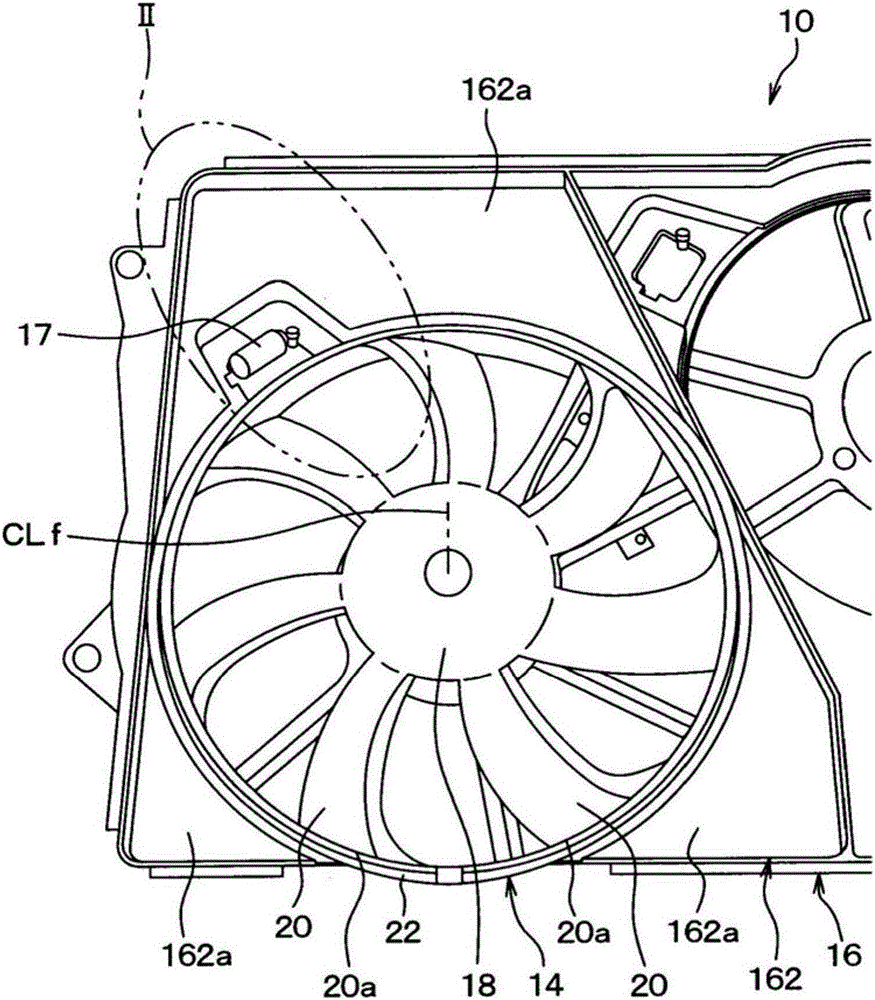
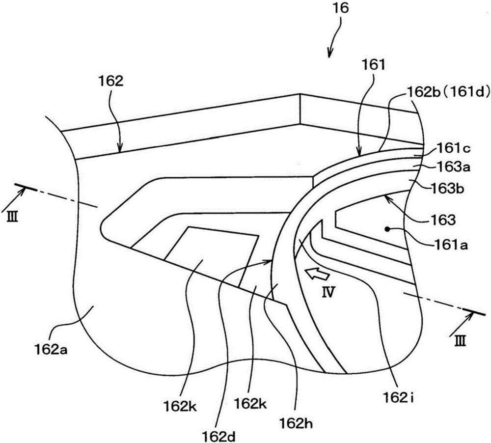
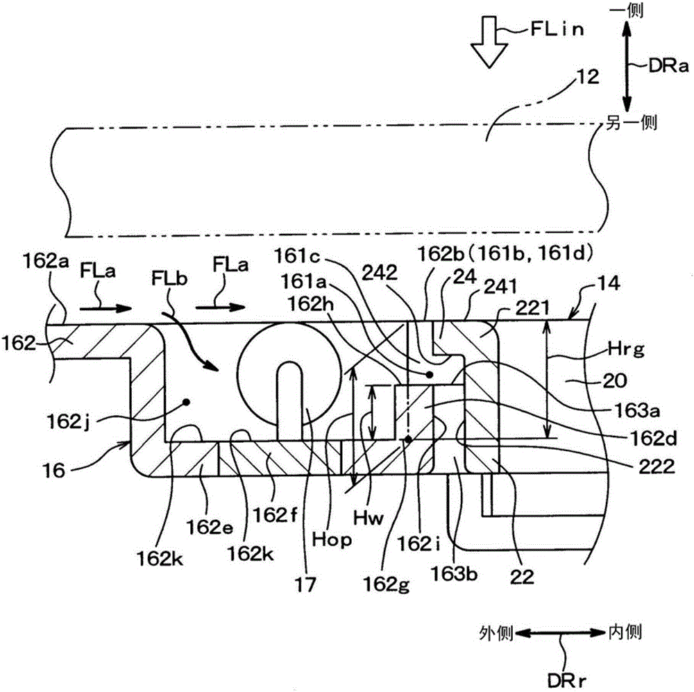
[0026] figure 1 A perspective view of a blower 10 with a fan cover 16 to which the present invention is applicable. figure 1 The blower 10 shown in is an axial flow blower for vehicles, which makes the outside air (air) flow to the radiator 12 (refer to image 3 ). The radiator 12 is a heat exchanger for cooling the cooling water of the vehicle running engine by exchanging heat between outside air and the cooling water of the vehicle running engine.

[0027] Blower 10 is arranged behind the vehicle relative to radiator 12 . Specifically, the air blower 10 is arranged on the downstream side of the radiator 12 in the flow direction of the air passing through the radiator 12 . The air blowe...


PUM


Abstract

This fan shroud is provided with a housing section (161) and a duct section (162). A fan housing hole (161a) for housing a fan (14) is formed in the housing section. A recessed space (162j) for installing an electric component (17) therein is formed in the duct section. The recessed space is disposed adjacent to the fan housing hole. The duct section has a recessed bottom surface (162k) and a dividing wall (162d). The recessed bottom surface forms the bottom of the recessed space. The dividing wall projects toward one side in the axial direction from the recessed bottom surface and is arranged so as to separate the recessed space and the fan housing hole from each other. The dividing wall is formed such that wall height (Hw) from the base (162g) to the tip (162h) of the dividing wall in the axial direction is lower than height (Hop) from the base of the dividing wall to one end (161b) of the fan housing hole on one side in the axial direction.

Description

[0001] Cross-references to related applications [0002] This application is based on the JP Patent application 2014-237236 for which it applied on November 24, 2014, The content of the indication is taken in this application as a reference. technical field [0003] The present invention relates to the structure of the fan guard for directing air to the blower fan. Background technique [0004] In an electric blower driven to rotate by a motor, when the rotational speed of the fan is controlled by electrical components such as resistors, the electrical components are attached to the fan cover for air cooling of the electrical components. Therefore, a box-shaped box space for arranging electrical components needs to be formed in the air flow path of the fan cover. For example, the box space can be provided in the busbar part that guides the air to the fan as the air guide part. [0005] When the fan is driven to rotate, air flows along the bus bar of the fan case and is suc...

Claims


Application Information

Patent Timeline
IPC IPC(8): F01P11/10F04D29/54
CPCF01P11/10F04D29/54
Inventor 埋田敏光
Owner DENSO CORP
Why Eureka
Try Eureka