Check patentability & draft patents in minutes with Patsnap Eureka AI!

Engine rotation speed control device

A technology of engine speed and control device, applied in the direction of engine control, machine/engine, electrical control, etc., can solve problems such as problems with the convergence of engine speed

Inactive Publication Date: 2017-02-22
AISIN SEIKI KK
View PDF6 Cites 4 Cited by
  • Summary
  • Abstract
  • Description
  • Claims
  • Application Information

AI Technical Summary

Problems solved by technology

In addition, in the conventional control device, the throttle opening is controlled only when the actual engine speed exceeds the upper limit value (engine speed upper limit value), so there is a possibility that the engine speed may fluctuate near the upper limit value. (hunting) or overshoot, there is a problem in the convergence of the engine speed to the target

Method used


Image

  • Engine rotation speed control device
  • Engine rotation speed control device
  • Engine rotation speed control device

Examples


Embodiment approach

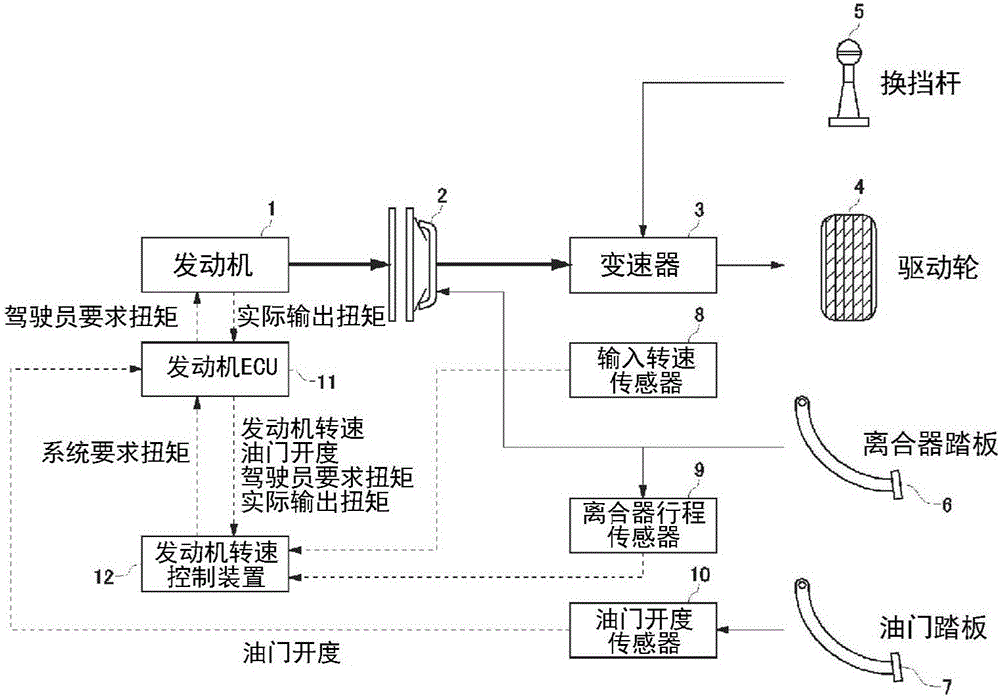
[0040] Hereinafter, an engine rotational speed control device according to an embodiment of the present invention will be described with reference to the drawings. In the present embodiment, the case of an engine rotational speed control device used in a vehicle or the like equipped with a manual transmission is exemplified.

[0041] The configuration of the engine rotational speed control device according to the embodiment of the present invention will be described with reference to the drawings. figure 1 It is a figure explaining the outline of the vehicle equipped with the engine rotational speed control apparatus of this embodiment. like figure 1 As shown, the vehicle has an engine 1 , a clutch 2 and a transmission 3 . The engine 1 is one of known internal combustion engines, and is, for example, a gasoline engine using gasoline as a fuel or a diesel engine using light oil as a fuel. The transmission 3 is, for example, a manual transmission having a plurality of (for ex...


PUM


Abstract

An engine rotation speed control device is provided with a target engine rotation speed calculation unit that calculates a target engine rotation speed depending on an accelerator opening of a vehicle, a torque gain calculation unit that calculates a torque gain on the basis of an amount of change in actual engine rotation speed and an attainment rate of the actual engine rotation speed with respect to the target engine rotation speed, and a system request torque calculation unit that calculates a system request torque on the basis of a value obtained by multiplying a driver request torque by the torque gain. The system request torque calculated in this way is requested to be output from the engine of the vehicle during engine rotation speed control.

Description

technical field [0001] The present invention relates to an engine speed control device for controlling the engine speed of a vehicle, and more particularly, to a technology for appropriately controlling the engine speed in response to stepping on an accelerator pedal (driver's operation). Background technique [0002] Generally, in a vehicle having a manual transmission, when starting, the driver first steps on the clutch pedal to change the clutch from the transmission state to the disengaged state, and then operates the shift lever to move the transmission mechanism to 1st speed. Then, while stepping on the accelerator pedal to increase the engine speed, the clutch pedal is gradually returned, and the clutch is gradually shifted from the disengaged state to the transmission state. At this time, the driver needs to coordinate the operation of the clutch pedal and the operation of the accelerator pedal. However, it is not easy for all drivers to coordinate the operation of t...

Claims


Application Information

Patent Timeline
Patent Type & Authority Applications(China)
IPC IPC(8): F02D45/00
CPCF02D45/00F02D41/0097F02D41/02F02D31/001F02D35/0007F02D2041/1422F02D2200/1002F02D2200/101F02D2200/1012F02D2200/602
Inventor 冈田太郎
Owner AISIN SEIKI KK
Features
  • R&D
  • Intellectual Property
  • Life Sciences
  • Materials
  • Tech Scout
  • Unparalleled Data Quality
  • Higher Quality Content
  • 60% Fewer Hallucinations
Learn More