
Carburetor with novel starter fuel system

A technology of carburetor and oil system, applied in the direction of carburetor, charging system, engine components, etc., can solve the problems of high cost and complex structure of carburetor, and achieve low cost, less machining process and tool conversion Effects of operation and fewer assembly steps

Active Publication Date: 2017-02-22
JIANGMEN HUALIAN IND
View PDF9 Cites 4 Cited by
  • Summary
  • Abstract
  • Description
  • Claims
  • Application Information

AI Technical Summary

Problems solved by technology

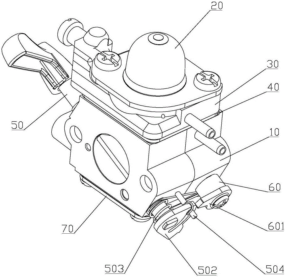
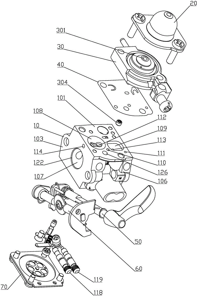
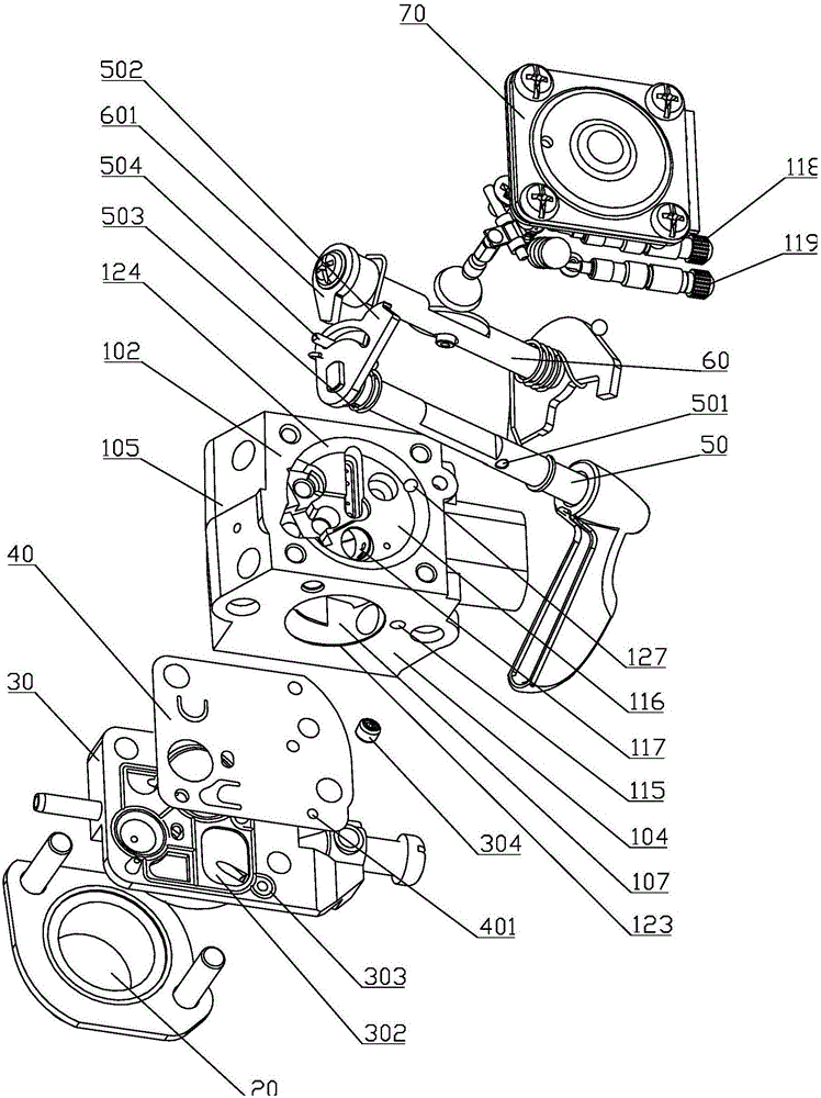
[0006] In order to solve the problem of complex structure and high cost of the carburetor in the prior art, the invention discloses a carburetor with a new type of starting oil system, which includes oil bubbles of the oil injector, pump cover, pump diaphragm, carburetor The body of the carburetor, the starting shaft, the throttle shaft and the metering chamber cover. The oil bubble, the pump cover and the pump diaphragm are successively fixed on the pump surface of the carburetor body by bolts. The carburetor body is provided with a mixing chamber, and the mixing chamber is provided with a metering chamber surface, There are three openings on the end surface of the throttle valve and the end surface of the choke valve. The starting shaft and the throttle valve shaft are installed obliquely in the carburetor body through the mixing chamber, and the two ends protrude from the oil inlet connection surface and the high and low speed nail surface respectively. The metering chamber cover is fixed on the metering chamber surface of the carburetor body by bolts

Method used


Image

  • Carburetor with novel starter fuel system
  • Carburetor with novel starter fuel system
  • Carburetor with novel starter fuel system

Examples


Embodiment Construction

[0028] The technical solutions in the embodiments of the present invention will be clearly and completely described below with reference to the accompanying drawings in the embodiments of the present invention. Obviously, the described embodiments are only a part of the embodiments of the present invention, but not all of the embodiments.

[0029] like Figure 1 to Figure 3 As shown, a carburetor with a new type of starting oil system includes an oil injector oil bubble 20, a pump cover 30, a pump diaphragm 40, a carburetor body 10, a starting shaft 50, a throttle shaft 60 and a metering chamber cover 70 . The carburetor body 10 is provided with a pump surface 101, a metering chamber surface 102, a throttle end surface 103, a choke end surface 104, an oil inlet connection surface 105, and a high and low speed nail surface 106, an oil injector oil bubble 20, a pump cover 30 and a pump membrane The pieces 40 are sequentially fixed on the pump surface 101 of the carburetor body ...


PUM


Abstract

Disclosed is a carburetor with a starter fuel system, which comprises a fuel pocket of a fuel injector, a pump cover, a pump diaphragm, a carburetor body (10), a starting shaft, a throttle shaft (60) and a metering chamber cover, wherein the carburetor body is provided with a pump face (101), a metering chamber face (102), a throttle end face (103), a choke valve end face (104), a fuel inlet connection face (105) and a high and low speed nailing face (106); the fuel pocket of the fuel injector, the pump cover and the pump diaphragm are fixedly provided on the pump face of the carburetor body (10) in a successive manner via a bolt; a mixing chamber (107) is provided in the carburetor body (10); the starting shaft and the throttle shaft (60) penetrate through the mixing chamber and are provided obliquely in the carburetor body (10) with two ends respectively extending out of the fuel inlet connection face (105) and the high and low speed nailing face (106); and the metering chamber cover is fixedly provided on the metering chamber face (102) of the carburetor body (10) via a bolt. The carburetor does not need a secondary fuel pump, a fuel inlet and outlet check valve system, a fuel control orifice and a pulse control orifice and the like, and also does not need an air channel for preventing the fuel from being pumped out due to a crankshaft negative pressure, and the present invention has low costs and a simple structure.

Description

technical field [0001] The invention relates to the technical field of carburetors, in particular to a carburetor with a novel starting oil system. Background technique [0002] Most engines require a mixture (air / fuel) enrichment system to improve engine running or to allow the engine to start, especially when the engine is running cold or running out of fuel. Under today's low emission requirements, the engine's excess air ratio (λ) is already close to 1, and the starting performance of almost every engine benefits from this. In the field of carbureted engines there are three methods to achieve mixture enrichment: choke system, oiler system, and fuel enrichment system. [0003] The choke valve system closes the front end of the carburetor intake port through the door to concentrate the mixture, allowing the negative pressure to draw more fuel from the oil passage in the opening direction of the intake hole, but the disadvantage of the choke valve system is that the user m...

Claims


Application Information

Patent Timeline
Patent Type & Authority Applications(China)
IPC IPC(8): F02M1/16F02M7/12F02M19/00
CPCF02M1/00F02M1/16F02M7/12F02M19/00
Inventor 陈献祥
Owner JIANGMEN HUALIAN IND
Learn More