Automatic in-situ registration and calibration of robotic arm/sensor/workspace system

A robot arm, sensor coordinate system technology, applied in the direction of robots, control/regulation systems, general control systems, etc., can solve problems such as less ideal ability to achieve precise placement of end effectors, and the complexity of typical methods.

Active Publication Date: 2017-02-22
MICROSOFT TECH LICENSING LLC
View PDF5 Cites 6 Cited by
  • Summary
  • Abstract
  • Description
  • Claims
  • Application Information

AI Technical Summary

Problems solved by technology

According to yet another example, a robotic arm may have a less than ideal ability to achieve precise placement of the end effector of such a robotic arm at desired Cartesian coo

Method used


Image

  • Automatic in-situ registration and calibration of robotic arm/sensor/workspace system
  • Automatic in-situ registration and calibration of robotic arm/sensor/workspace system
  • Automatic in-situ registration and calibration of robotic arm/sensor/workspace system

Examples


example 1

[0104] Example 1: A method of controlling a depth sensor and a robotic arm operating in a workspace, the robotic arm including an end effector, the method comprising: receiving an input point from the depth sensor, the input point including an indication in a sensor coordinate system The coordinates of the location of , which is in the workspace; identify the sensor calibration point in the vicinity of the input point, the sensor calibration point includes the first coordinate of the end effector in the sensor coordinate system, the first coordinate is previously in the end effector Collected during calibration at a given position within the workspace; identifying arm calibration points corresponding to sensor calibration points, respectively, including the position of the end effector in the arm coordinate system second coordinates, the second coordinates were previously collected during calibration with the end effector at a given position within the workspace; and employing ...

example 2

[0105]Example 2: The method of Example 1, further comprising performing a calibration, the performing of the calibration comprising: causing the end effector to traverse the work zone non-continuously based on a pattern, wherein the end effector operates according to the pattern stopping at positions within the zone; and at each of the positions from within the work zone at which the end effector stopped: collecting a position of the end effector within the work zone for detection by the depth sensor The sensor calibration point for the position includes the coordinates of the end effector in the sensor coordinate system at that position in the workspace; and the sensor calibration point for the end effector detected by the robot arm in the workspace The arm calibration point for a location, the arm calibration point for a location includes the coordinates in the arm coordinate system of the end effector at that location within the workspace.

example 3

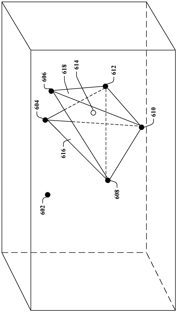
[0106] Example 3: The method of Example 2, further comprising calculating a centroid based on image moments of the standard deviation image from the depth sensor, the coordinates of the sensor calibration point being the coordinates of the centroid.


PUM


Abstract

Various technologies described herein pertain to automatic in-situ calibration and registration of a depth sensor and a robotic arm, where the depth sensor and the robotic arm operate in a workspace. The robotic arm can include an end effector. A non-parametric technique for registration between the depth sensor and the robotic arm can be implemented. The registration technique can utilize a sparse sampling of the workspace (e.g., collected during calibration or recalibration). A point cloud can be formed over calibration points and interpolation can be performed within the point cloud to map coordinates in a sensor coordinate frame to coordinates in an arm coordinate frame. Such technique can automatically incorporate intrinsic sensor parameters into transformations between the depth sensor and the robotic arm. Accordingly, an explicit model of intrinsics or biases of the depth sensor need not be utilized.

Description

Background technique [0001] Manipulation of objects can be a function of a large class of robotic systems (eg, manipulation systems). For example, a typical closed-loop manipulation system may include at least one optical sensor (e.g., a depth sensor) that senses and interprets a real-world scene and a physical manipulator (e.g., actuators, robotic arms, etc.). The ability to perform a useful task with a physical object may depend on the ability of a robotic arm to manipulate the object with sufficient accuracy for that task. This accuracy may depend on the mapping between the coordinate system of the depth sensor and the coordinate system of the robot arm. For example, a mapping may be created between coordinates extracted from a depth image generated by a depth sensor and the Cartesian position of the robot arm in the workspace. Such mapping between coordinate systems may also be referred to as registration. Precise and accurate mapping between depth sensors and robotic ...

Claims


Application Information

Patent Timeline
IPC IPC(8): G01B21/00B25J19/00
CPCB25J9/1692B25J9/1674B25J9/1694B25J9/1697G05B2219/39016G05B2219/39021G05B2219/39022G05B2219/39367G05B2219/40607Y10S901/09G01B21/00B25J19/00
Inventor G.施拉延M.雷沃夫M.贾罗比努B.J.蒂博多
Owner MICROSOFT TECH LICENSING LLC
Why Eureka
Try Eureka