Switched-mode power supply unit

A power grid and switch technology, applied in the field of switch grid components, can solve the problems of limiting the maximum power difference of converters, high component costs, etc., and achieve the effect of good balance and multiple losses

Inactive Publication Date: 2017-02-22
SIEMENS AG
View PDF4 Cites 1 Cited by
  • Summary
  • Abstract
  • Description
  • Claims
  • Application Information

AI Technical Summary

Problems solved by technology

With narrow regulations on tolerances it is possible to: limit the maximum power difference of the converter
However, this measure is associated with corresponding expenditures (eg higher component costs)

Method used


Image

  • Switched-mode power supply unit
  • Switched-mode power supply unit
  • Switched-mode power supply unit

Examples


Embodiment Construction

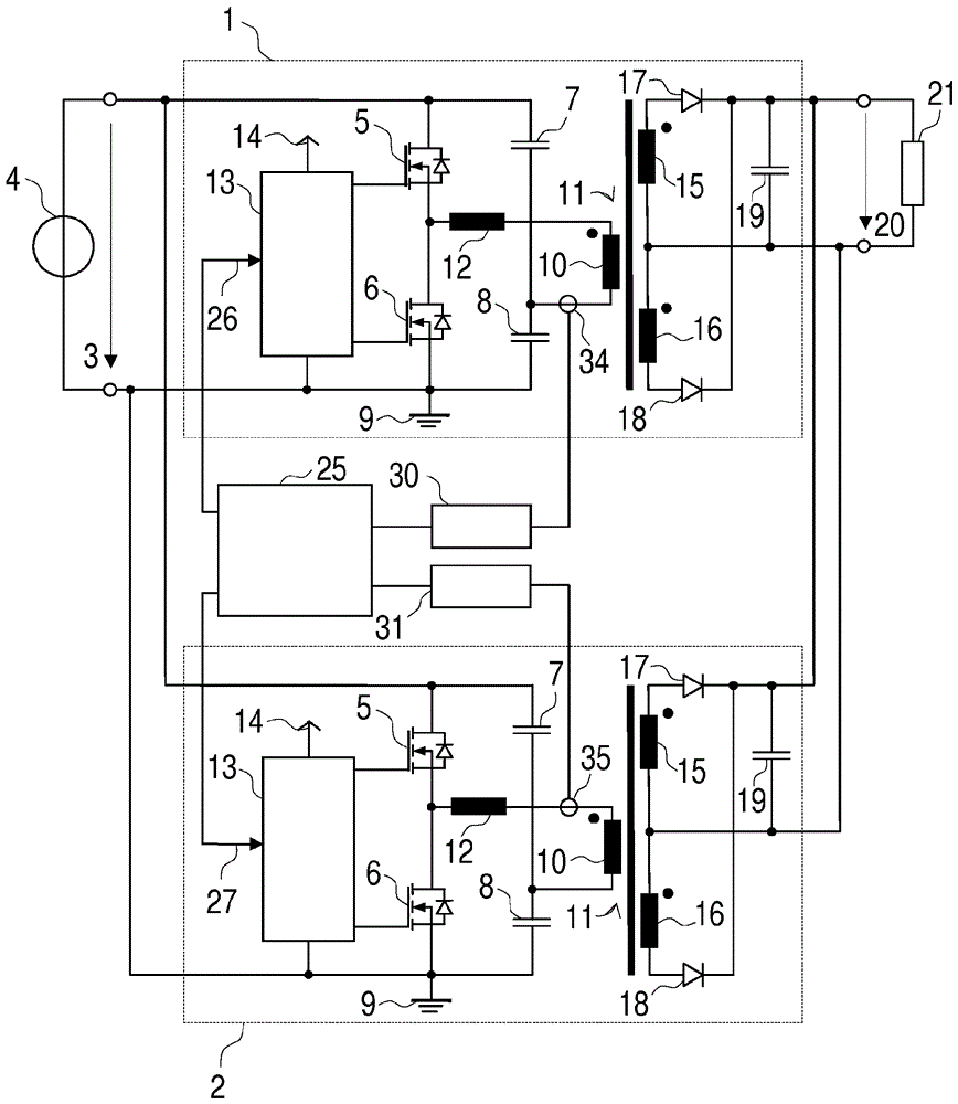
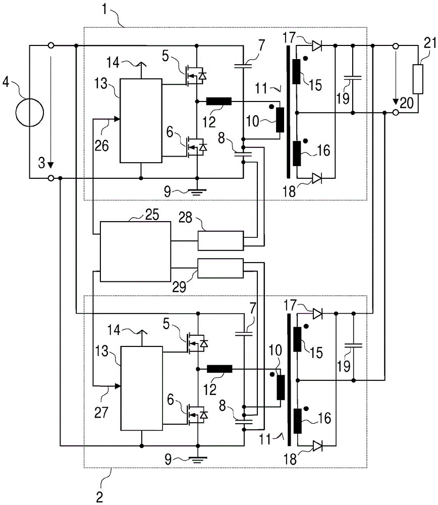
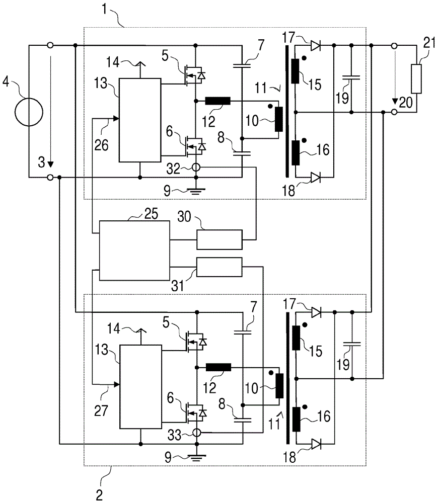
[0033] The parallel connection of the two LLC resonant converters 1 , 2 is applied to a common input voltage 3 . The voltage source 4 is, for example, a rectified mains voltage. The corresponding half-bridge circuit consists of two switching elements 5 , 6 and two resonant capacitors 7 , 8 and is connected on the input side to the input voltage 3 . In this case, the input voltage 3 is relative to ground potential 9 . At the output of the half-bridge circuit, a primary winding 10 of a transformer 11 is arranged in series with a resonant inductance 12 . The resonant inductance 12 may be its own coil or may be the leakage inductance of the transformer 11 .

[0034] The two switching elements 5 , 6 are actuated by means of the actuation circuit 13 . The control circuit 13 generates control pulses, which are transmitted galvanically split to the power components of the resonant converters 5 , 6 , for example by means of a control transmitter. The control circuit 13 is connected...


PUM


Abstract

The invention relates to a switched-mode power supply unit comprising at least two LLC resonant converters (1, 2) which are connected in parallel and each of which includes a test circuit (22, 23, 28, 29, 30, 31) generating a test signal that is proportionate to the transmitted current of the associated LLC resonant converter (1, 2); each test signal is fed to a load controller (25) which modifies at least one switching frequency of an LLC resonant converter (1, 2) in such a way that the test signals converge. This allows the current or load to be accurately split when a plurality of LLC resonant converters (1, 2) is connected in parallel.

Description

technical field [0001] The invention relates to a switched grid component comprising at least two parallel-connected LLC resonant converters and a method for regulating the switched grid component. Background technique [0002] Thus, the name LLC resonant converter mentions (ruehren): Two inductors and a capacitor form a resonant tank. Specifically, the magnetizing inductance and scattering inductance (leakage inductance) of the transformer and the capacitance of the resonant capacitor. In this case, parasitic effects that would otherwise be undesirable are exploited in a targeted manner by the specific design of the transformer. Occasionally, if the leakage inductance of the transformer is insufficient, then an own resonant coil arrangement is made. This results in high efficiencies and a small structural size in the case of LLC resonant converters. [0003] The LLC resonant converter is driven with a switching frequency which determines the conversion ratio and thus the...

Claims


Application Information

Patent Timeline
Patent Type & Authority Applications(China)
IPC IPC(8): H02M3/335
CPCH02M3/335H02M3/285Y02B70/10Y02P80/10H02M1/0058H02M7/4815G01K13/00G01R15/146G01R19/2513H02M3/33546
Inventor J.戴茨夫斯基S.雷舍瑙尔S.舒尔茨
Owner SIEMENS AG
Why Eureka
Try Eureka