Inner pot for rice cooker, rice cooker and method for manufacturing inner pot
A technology for a rice cooker and an inner pot is applied in the directions of chemical instruments and methods, applications, kitchen utensils, etc., which can solve the problems of indistinguishable, affecting the use effect, uneven spraying on the outer surface of the pot wall, etc., and achieves the effect of beautiful appearance.
- Summary
- Abstract
- Description
- Claims
- Application Information
AI Technical Summary
Problems solved by technology
Method used
Image
Examples
Embodiment approach 1
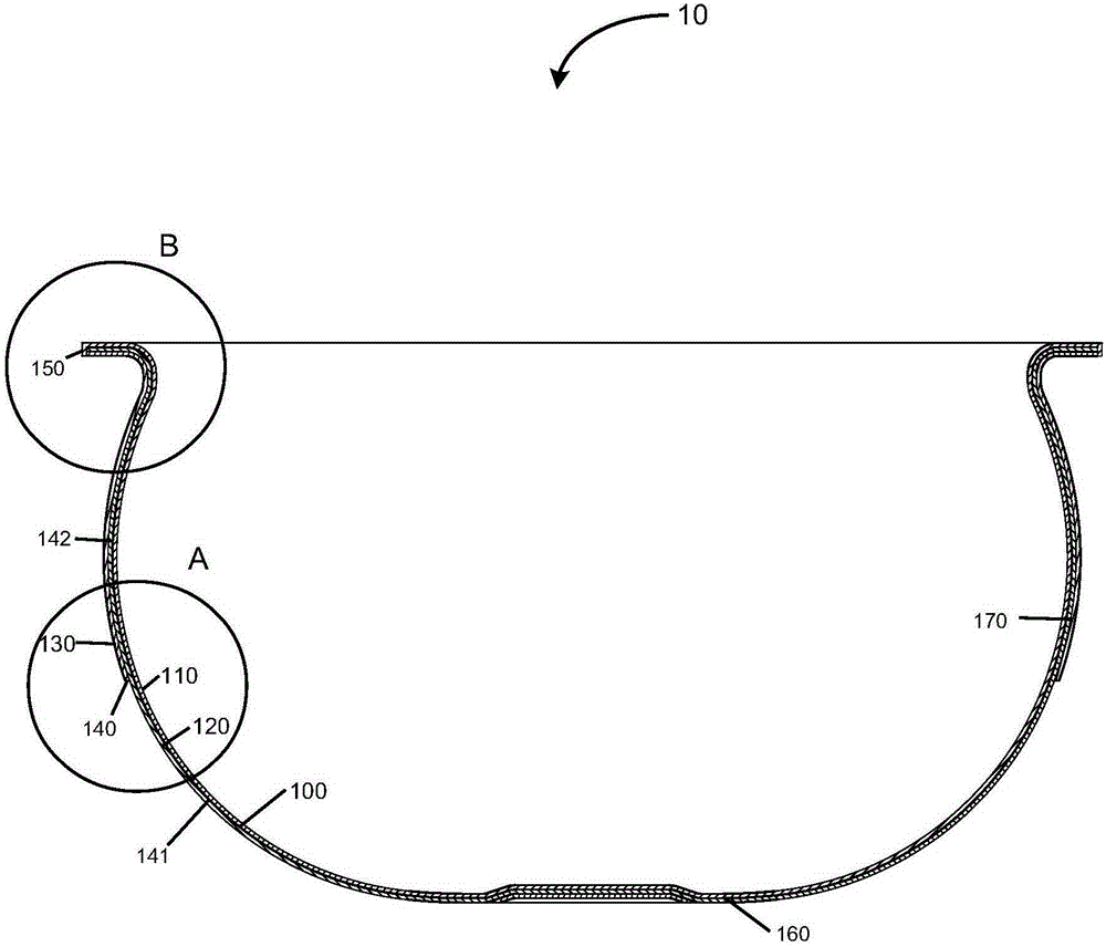
[0038] Below, refer to Figure 1 to Figure 7 A preferred embodiment of the present invention will be described. The inner pot according to the present invention can be applied to a rice cooker such as an electric rice cooker, an electric pressure cooker or other electric heating cookers. It should be understood that, in addition to the function of cooking rice, the above-mentioned rice cooker may also have functions such as porridge cooking and soup cooking. Hereinafter, the inner pot according to the present invention will be described in detail.
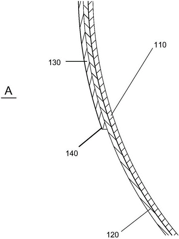
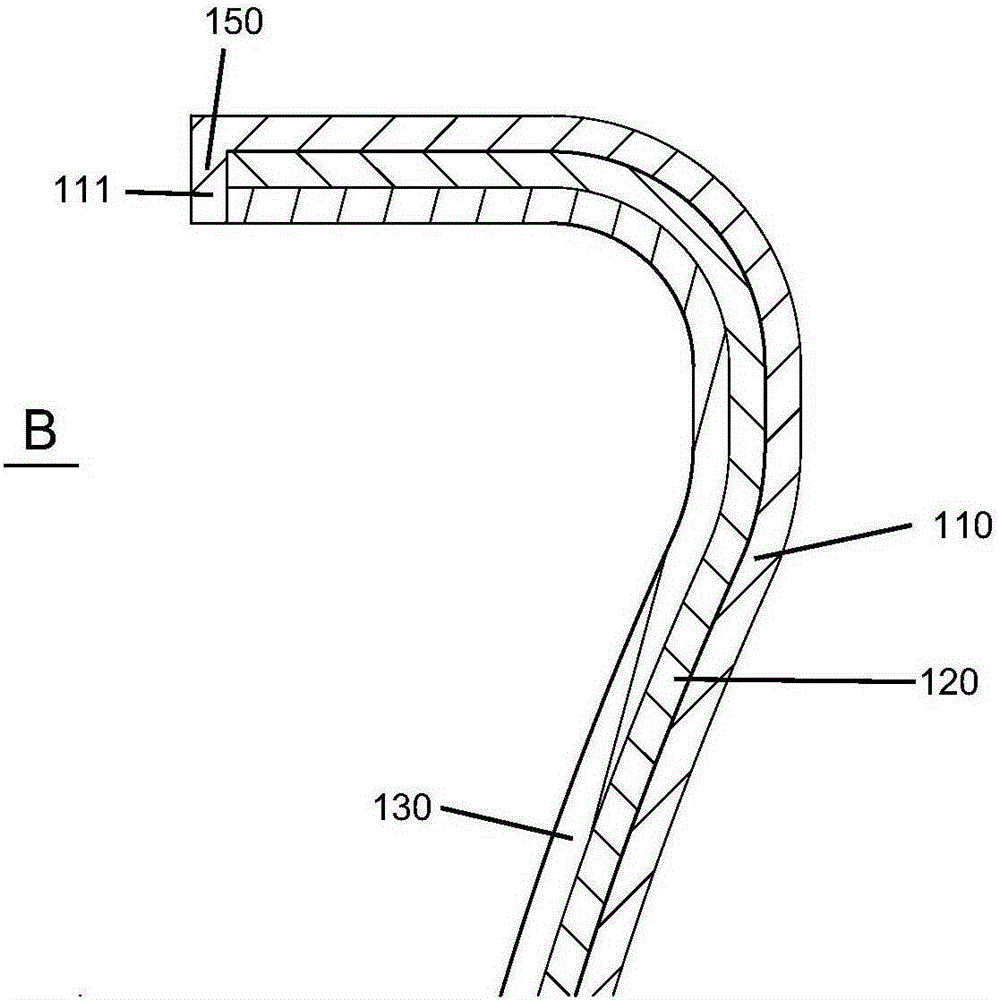
[0039] like figure 1 As shown, the inner pot 10 is surrounded by a pot wall 100. The pot wall 100 forms a top opening at its top. The pot wall 100 includes a substantially cylindrical side wall 170 and a substantially circular bottom wall 160. The bottom wall 160 is connected to The lower part of the side wall 170 and the top of the side wall 170 form the top opening, and the bottom wall 160 and the side wall 170 together form t...
Embodiment approach
[0048] Firstly, step S1 (i.e. pressing step) is performed to press the thermally conductive layer 110, the magnetically conductive layer 120 and the protective layer 130 together to form a composite sheet, wherein the magnetically conductive layer 120 is formed between the thermally conductive layer 110 and the protective layer 130 between.
[0049] Then step S2 (that is, the stretching step) is performed, and the composite plate formed in step S1 is put into the mold of the stretching device for stretching, so as to preliminarily form an inner pot with the heat-conducting layer 110 as the inner surface. It can be understood that after the stretching step, the opening of the preliminarily formed inner pot can be adjusted to the required size R angle, and the excess trim can be cut off.
[0050] Then perform step S3 (i.e. the expanding step), put the stretched composite plate into the expanding equipment mold and expand, so that the inner pot can form a predetermined shape and ...
Embodiment approach 2
[0060] Refer to the following Figure 8 Another preferred embodiment of the present invention will be described. For the purpose of simplification, when describing the second embodiment, the description of the same parts as those of the first embodiment is omitted.
[0061] Figure 8 is a schematic diagram according to the second preferred embodiment of the present invention. like Figure 8 As shown, the difference between Embodiment 2 and Embodiment 1 is that the pot wall 200 only includes a heat conduction layer 210 disposed inside and a magnetic conduction layer 220 disposed outside the heat conduction layer 210 , without a protective layer. It can be understood that since the magnetic permeable layer 220 is disposed outside in this embodiment, in order to prevent the magnetic permeable layer 220 from rusting, the magnetic permeable layer 220 can be made of a material with good magnetic permeation effect and not easy to rust, such as stainless steel.
[0062] like Fig...
PUM
| Property | Measurement | Unit |
|---|---|---|
| thickness | aaaaa | aaaaa |
Abstract
Description
Claims
Application Information
 - R&D
- Intellectual Property
- Life Sciences
- Materials
- Tech Scout
- Unparalleled Data Quality
- Higher Quality Content
- 60% Fewer Hallucinations
Browse by: Latest US Patents, China's latest patents, Technical Efficacy Thesaurus, Application Domain, Technology Topic, Popular Technical Reports.
© 2025 PatSnap. All rights reserved.Legal|Privacy policy|Modern Slavery Act Transparency Statement|Sitemap|About US| Contact US: help@patsnap.com


