Train-braking impulse control method

A pulse control, train technology, applied in the direction of brakes, pneumatic brakes, brake transmission devices, etc., can solve the problem of inability to stabilize the exhaust air speed control, and achieve the effect of stable speed

Active Publication Date: 2017-03-01
HANGZHOU CHUANGLIAN ELECTRONICS TECH
View PDF2 Cites 5 Cited by
  • Summary
  • Abstract
  • Description
  • Claims
  • Application Information

AI Technical Summary

Problems solved by technology

[0006] The purpose of the invention is to provide a pulse control method for train braking that can realize stable air exhaust and speed control in

Method used


Image

  • Train-braking impulse control method
  • Train-braking impulse control method
  • Train-braking impulse control method

Examples


Embodiment 1

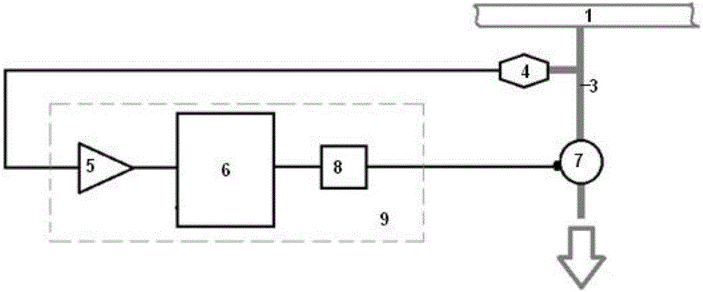
[0055] Such as figure 1 The illustrated embodiment is a pulse control method for train braking, comprising a train pipe 1 arranged on the train, a controller 2, a pipeline 3 communicated with the train pipe, a pressure sensor 4 arranged on the pipeline, and an AD conversion Device 5, processor 6, solenoid valve 7 and solenoid valve drive circuit 8 located at the rear of the exhaust port of the pipeline; the signal output end of the pressure sensor, AD converter, processor, drive circuit and solenoid valve are electrically connected in turn. connection; the controller is electrically connected to the processor; the AD converter, the processor and the drive circuit are all located in the train control vehicle-mounted device 9;

[0056] Including the following steps:

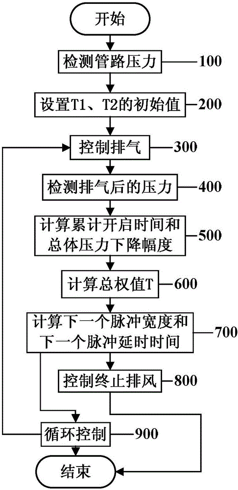
[0057] Such as figure 2 As shown, step 100, detecting pipeline pressure

[0058] The pressure sensor detects the pressure in the pipeline, the controller sends an exhaust command to the processor, and the proce...

Embodiment 2

[0084] Embodiment 2 includes all the structures and method parts of Embodiment 1, and Embodiment 2 also includes a microprocessor located between the pressure sensor and the first signal amplifier, and also includes the following steps:

[0085] In the microprocessor, the detection signal of the pressure sensor is processed as follows:

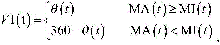
[0086] For each moment t in the detection signal, the computer calculates the voltage amplitude mean value VU(t), the voltage amplitude maximum value MA(t) and the voltage amplitude minimum value MI(t) from the time t-T to the time t;

[0087] set up

[0088]

[0089]

[0090]

[0091]

[0092] in,

[0093] The microprocessor sends the corrected detection signal V(t) to the first signal amplifier.


PUM


Abstract

The invention discloses a train-braking impulse control method. The train-braking impulse control method relates to a train pipe arranged on a train, a controller, a pipe communicated with the train pipe, a pressure sensor arranged on the pipe, an AD convertor, a processor, an electromagnetic valve arranged at the back portion of an air discharging opening of the pipe and a driving circuit of the electromagnetic valve; the signal output end of the pressure sensor, the AD convertor, the processor, the electromagnetic valve of the driving circuit are sequentially and electrically connected; the controller is electrically connected with the processor. The train-braking impulse control method has the advantages that the pulse separation and the pulse width can be calculated according to variation of pipe pressure, and the train can reduce pressure at the stable rate.

Description

technical field [0001] The invention relates to the technical field of rail vehicle braking, in particular to a pulse control method for train braking capable of realizing stable wind exhaust and speed control. Background technique [0002] The braking method of rail vehicles mainly adopts the air brake system. During the operation of the vehicle, the driver manipulates the brake valve to discharge the air in the train pipe, so that the pressure of the train pipe decreases, and the brake of the vehicle is controlled to achieve the purpose of deceleration and parking. [0003] When the vehicles are formed into a train, the train pipes of each car are connected into one body, and the pressure in the train pipe is controlled by the locomotive driver to achieve the purpose of controlling the synchronous braking and relief of the whole train. [0004] The on-board train control equipment is a kind of on-board safety equipment configured on the locomotive. It mainly includes GYK, ...

Claims


Application Information

Patent Timeline
IPC IPC(8): B61H11/06B60T8/172B60T11/224
CPCB60T8/1705B60T8/172B60T11/224B61H11/06
Inventor 贾幼尧俞仲勋朱有田
Owner HANGZHOU CHUANGLIAN ELECTRONICS TECH
Why Eureka
Try Eureka