Optical detection apparatus for preventing light leakage

A detection device and light detection technology, which are applied in measurement devices, material analysis by optical means, scientific instruments, etc. inter-structure and other issues

Active Publication Date: 2017-03-01
PIXART IMAGING INC
View PDF5 Cites 3 Cited by
  • Summary
  • Abstract
  • Description
  • Claims
  • Application Information

AI Technical Summary

Problems solved by technology

Although the light sensing module uses two sets of lens structures (component number 715) to guide the signal transmitter to emit sensing light and guide the sensing light reflected from the object to be read by the signal receiver, but the signal receiver and the signal There is no compartment structure in the middle ...

Method used


Image

  • Optical detection apparatus for preventing light leakage
  • Optical detection apparatus for preventing light leakage
  • Optical detection apparatus for preventing light leakage

Examples


Embodiment Construction

[0044] It should be understood that the specific embodiments described here are only used to explain the present invention, not to limit the present invention.

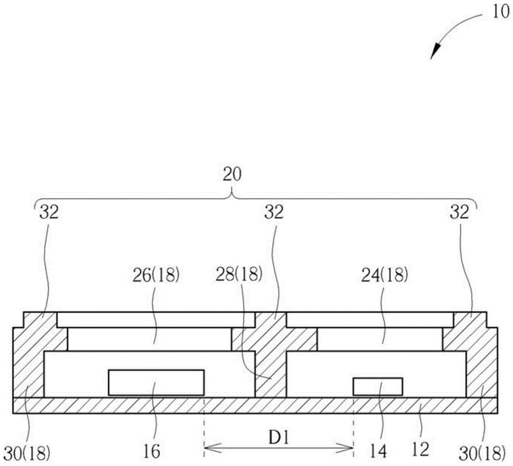
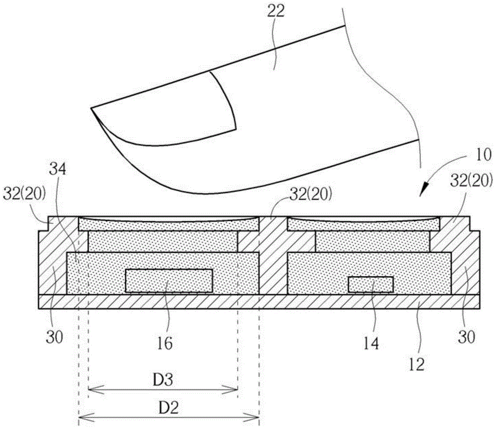
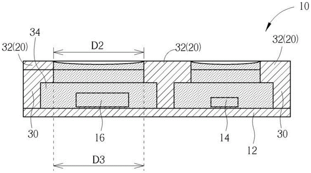
[0045] see figure 1 and figure 2 , figure 1 and figure 2 They are schematic diagrams of different manufacturing processes of the optical detection device 10 according to the first embodiment of the present invention. The optical detection device 10 includes a circuit substrate 12 , a light source 14 , a light detection component 16 , a packaging structure 18 and a light-shielding element 20 . The optical detection device 10 is generally installed on wearable devices such as smart watches and smart bracelets. The circuit substrate 12 can be independent of the wearable device, or it can be part of the wearable device, depending on the design requirements. Certainly. The light source 14 is disposed on the circuit substrate 12 and is used for outputting an imaging signal to irradiate the object 22 to be measured....


PUM


Abstract

The invention discloses an optical detection apparatus for preventing light leakage. The optical detection apparatus comprises a light source, an optical detection assembly, a packaging structure and a shading member. A sampling signal is output by the light source to irradiate a to-be-measured object. The optical detection assembly is arranged next to the light source, and keeps a distance with the light source. The optical detection assembly is used for receiving the sampling signal reflected by the to-be-measured object. The packaging structure is used for coating the light source and the optical detection assembly. The packaging structure comprises an out-light surface unit and an in-light surface unit which are respectively arranged on the light source and the optical detection assembly. The packaging structure also comprises a segmentation member which is arranged between the in-light surface unit and the out-light surface unit. The shading member is arranged on the segmentation member for blocking that the sampling signal is projected to the in-light surface unit without reflection by the to-be-measured object.

Description

technical field [0001] The invention provides an optical detection device, especially an optical detection device capable of preventing light leakage. Background technique [0002] Traditional light sensing modules are prone to poor sensing accuracy due to light leakage. The reason is usually that the light isolation mechanism of the light sensing module is not well designed. Part of the light signal will be directly transmitted to the light-receiving component, and the light-receiving component will read light signals other than non-sensing light, which will degrade the signal quality and affect the sensing accuracy. For example, US patent US 8,888,701, according to which Figure 7-8 As shown, the light sensing module is provided with a signal transmitter (component number 102) and a signal receiver (component number 103) adjacent to each other. Although the light sensing module uses two sets of lens structures (component number 715) to guide the signal transmitter to emit...

Claims


Application Information

Patent Timeline
IPC IPC(8): G01N21/00
Inventor 赖宏昱黄郁湘赖鸿庆
Owner PIXART IMAGING INC
Why Eureka
Try Eureka