Vehicle tires

A technology for pneumatic tires and vehicles, applied in vehicle parts, tire parts, tire treads/tread patterns, etc., can solve the problems of lack of lateral rigidity, no display of operating characteristics, etc., and achieve the effect of high lateral rigidity

Active Publication Date: 2017-03-01
CONTINENTAL REIFEN DEUTSCHLAND GMBH
View PDF7 Cites 2 Cited by
  • Summary
  • Abstract
  • Description
  • Claims
  • Application Information

AI Technical Summary

Problems solved by technology

First of all, in the case of higher handling requirements of this tire, especially in the case of a sporty driving style, due to the lack of sufficient lateral stiffness, it does not show satisfactory handling characteristics

Method used


Image

  • Vehicle tires
  • Vehicle tires
  • Vehicle tires

Examples


Embodiment Construction

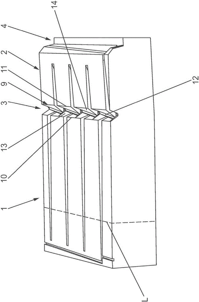
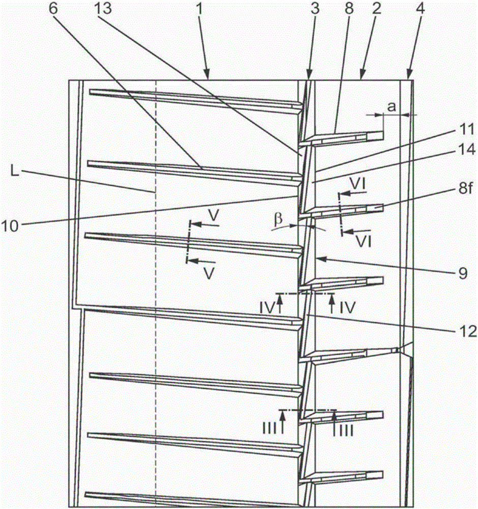
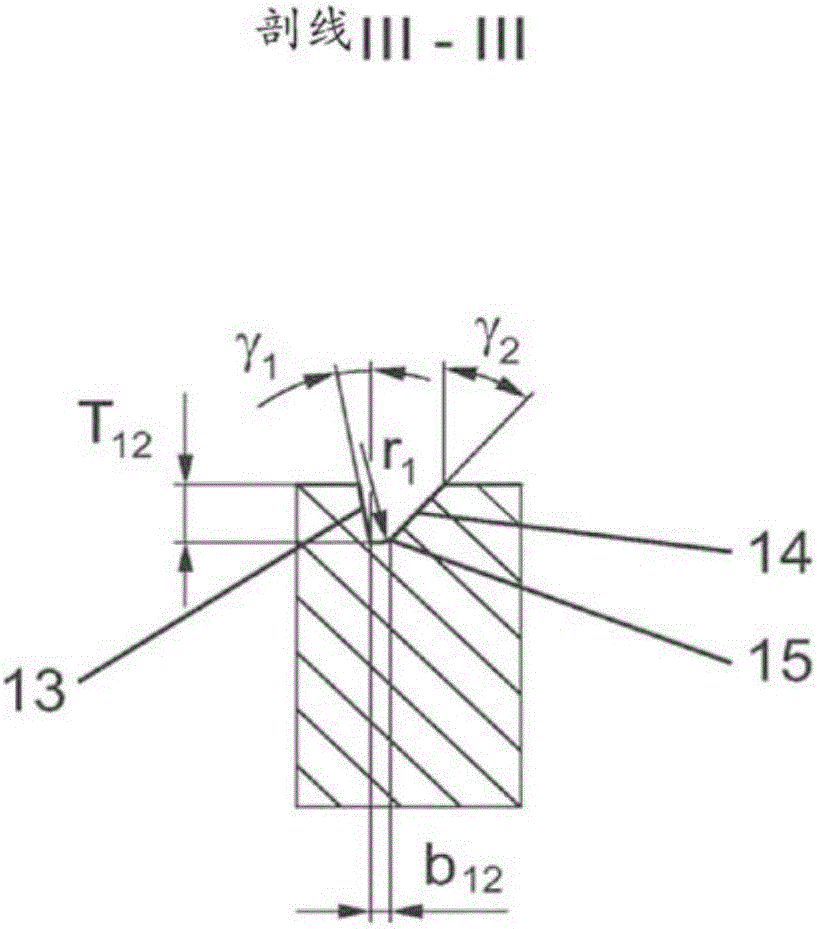
[0017] figure 1 and figure 2 A shoulder-side block row 1 and a block-structured tread band 2 are shown, particularly suitable for a vehicle pneumatic tire tread for passenger motor vehicles. The shoulder-side row of blocks 1 and the block-structured tread band 2 are arranged in particular in an outer subregion of a so-called “asymmetrical” tread pattern. Such tread patterns have, in the two tread halves, structurally differently configured profiles which are correspondingly implemented with respect to certain properties of the tire or tread. The shoulder-side row of blocks 1 is located at the outer shoulder of the tyre, which in a known manner is the shoulder-side area of ​​the tyre, which is at the tire mounted on the vehicle Visible at the outside of the vehicle. exist figure 1 and figure 2 The line L indicated in row 1 of blocks on the shoulder side of the tread marks the edge of the tread, more precisely the edge of the ground-contacting or ground-supporting surface...


PUM


Abstract

The invention relates to vehicle tires with a tread with a shoulder-side block row (1), which is separated from other block row through circumferential ridge (3) with parallel extending edges (10, 11). The circumferential ridge (3) is formed by circumferential portions (9) in which the ridge base (12) runs at an acute angle (beta) to the circumferential direction, wherein ridge flanks (13, 14) run between the ridge base (12) and the tread surface. In each circumferential portion (9), the angle of inclination (gamma 2) of the ridge flank (14) which can be found on the inside of the tread changes to a greater extent than the angle of inclination (gamma 1) of the opposite ridge flank (13)on the outer side of the tread.

Description

technical field [0001] The invention relates to a pneumatic tire for vehicles having a tread with shoulder-side rows of blocks passing through transverse grooves extending at least substantially in the transverse direction The tread blocks are separated from each other, and the block row is separated by a circumferential groove from a further block row or a tread band of block structure in which at least substantially a further transverse groove extending in the transverse direction, wherein the circumferential groove is delimited at the tread surface by two rims parallel to each other and extending in the circumferential direction and consists of circumferential sections in which The groove base correspondingly extends at an acute angle with respect to the circumferential direction and has an end disposed on the outside of the tread and an end disposed on the inside of the tread, wherein the groove sides are between the groove base and the tread surface The angle of inclinat...

Claims


Application Information

Patent Timeline
Patent Type & Authority Applications(China)
IPC IPC(8): B60C11/13B60C11/03
CPCB60C11/1315B60C11/0309B60C11/045B60C11/1323B60C11/0302B60C11/13B60C11/1384B60C11/1392
Inventor 乌尔里希·贝尔马库斯·菲舍尔
Owner CONTINENTAL REIFEN DEUTSCHLAND GMBH
Why Eureka
Try Eureka