
Lateral gas inlet structure for engine

An air intake structure and engine technology, which is applied in the direction of power plant gas intake, upper structure, and upper structure sub-assembly, etc., can solve the problems of abnormal combustion, limited heat dissipation space, and high combustion temperature of the engine, so as to reduce the content, The effect of improving the charging efficiency and reducing the combustion temperature

Active Publication Date: 2017-03-08
ANHUI JIANGHUAI AUTOMOBILE GRP CORP LTD
View PDF6 Cites 0 Cited by
  • Summary
  • Abstract
  • Description
  • Claims
  • Application Information

AI Technical Summary

Problems solved by technology

In the prior art, the engine air intake structure is usually arranged inside the engine, and the internal components of the engine and their installation structures are usually arranged closely, so that the heat dissipation space is limited, resulting in excessively high ambient temperature around the engine air intake structure, which affects the engine. In addition, it is easy to cause the engine combustion temperature to be too high, resulting in abnormal combustion such as deflagration, increasing the content of nitrogen oxides in the engine exhaust gas, and aggravating emission pollution

Method used


Image

  • Lateral gas inlet structure for engine
  • Lateral gas inlet structure for engine
  • Lateral gas inlet structure for engine

Examples


Embodiment Construction

[0027] Embodiments of the present invention are described in detail below, examples of which are shown in the drawings, wherein the same or similar reference numerals designate the same or similar elements or elements having the same or similar functions throughout. The embodiments described below by referring to the figures are exemplary only for explaining the present invention and should not be construed as limiting the present invention.

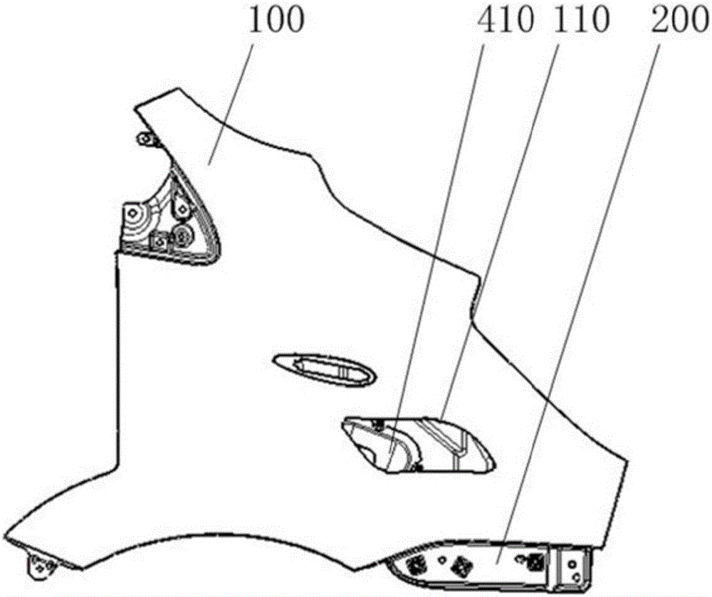
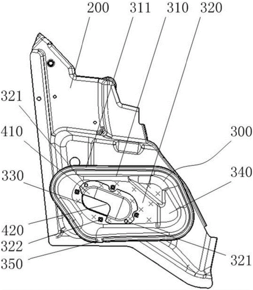
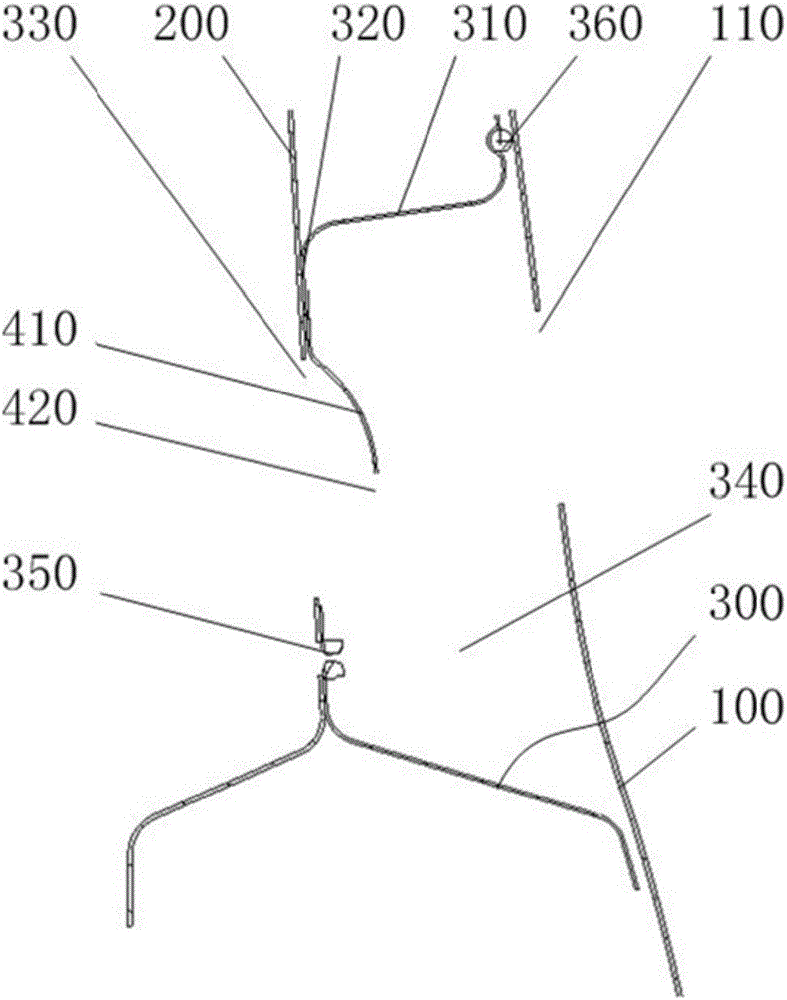
[0028] figure 1 The structural schematic diagram of the engine side air intake structure provided by the embodiment of the present invention, figure 2 is the state diagram of the air guide installed on the side panel of the engine compartment, image 3 A cross-sectional view of the engine side air intake structure provided by the embodiment of the present invention, Figure 4 It is a schematic diagram of the structure of the guide part.

[0029] Please also refer to Figure 1 to Figure 4 , the embodiment of the present invention pro...


PUM


Abstract

The invention discloses a lateral gas inlet structure for an engine. The lateral gas inlet structure comprises a guide part and a fender, wherein the guide part comprises a lateral plate and a bottom plate, the lateral plate and the bottom plate forms a gas inlet cavity in an enclosed manner, a first through hole is formed in the bottom plate, and the bottom plate is fixed to the lateral retaining plate of an engine cabin; one side, opposite to the bottom plate, of the guide part is fixedly arranged on the fender provided with a second through hole, and the second through hole is communicated with the gas inlet cavity. The lateral gas inlet structure has the advantages that an engine can take gas outside a vehicle body by the guide part and holes formed in the fender and the engine cabin lateral retaining plate, the gas filling efficiency of the engine is increased, the combustion temperature of the engine is lowered at the same time, and nitride oxide content in waste gas is reduced.

Description

technical field [0001] The invention relates to an engine air intake structure, in particular to an engine side air intake structure. Background technique [0002] The air intake structure of the engine is an important structure to ensure normal combustion in the engine. In the prior art, the engine air intake structure is usually arranged inside the engine, and the internal components of the engine and their installation structures are usually arranged closely, so that the heat dissipation space is limited, resulting in excessively high ambient temperature around the engine air intake structure, which affects the performance of the engine. In addition, it is easy to cause the engine combustion temperature to be too high, causing abnormal combustion such as deflagration, increasing the content of nitrogen oxides in the engine exhaust gas, and aggravating emission pollution. Contents of the invention [0003] The purpose of the present invention is to provide a side air in...

Claims


Application Information

Patent Timeline
IPC IPC(8): B60K13/02B62D25/16
CPCB60K13/02B62D25/16
Inventor 张龙陈晓春刘海霞
Owner ANHUI JIANGHUAI AUTOMOBILE GRP CORP LTD
Learn More