Spare tire lifter

A technology of a lifter and a lifting mechanism, which is applied in the field of vehicles, and can solve problems such as the spare tire falling and the inability to lock the position

Active Publication Date: 2017-03-08
SAIC MOTOR
View PDF5 Cites 2 Cited by
  • Summary
  • Abstract
  • Description
  • Claims
  • Application Information

AI Technical Summary

Problems solved by technology

[0006] The problem solved by the present invention is that when the existing spare tire lifter lifts the spare tire, if the power source is removed, the spare tire will fall, and the position cannot be locked

Method used


Image

  • Spare tire lifter
  • Spare tire lifter
  • Spare tire lifter

Examples


Embodiment Construction

[0036] In order to make the above objects, features and advantages of the present invention more comprehensible, specific embodiments of the present invention will be described in detail below in conjunction with the accompanying drawings.

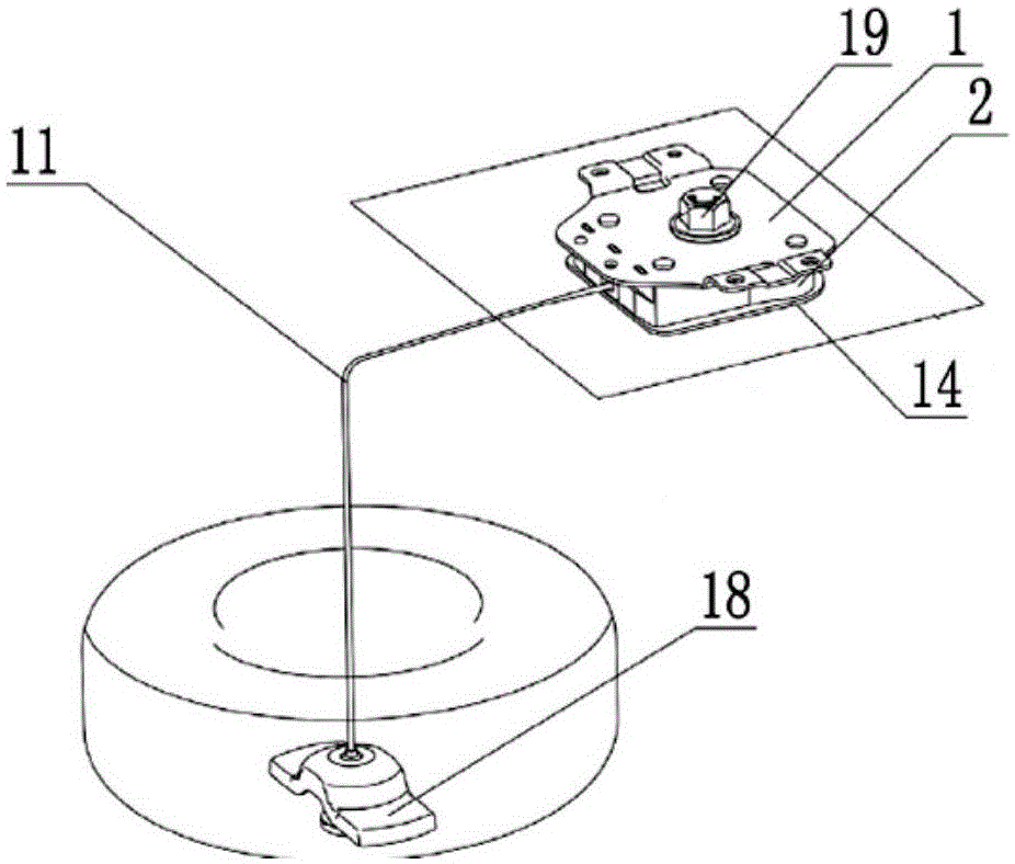
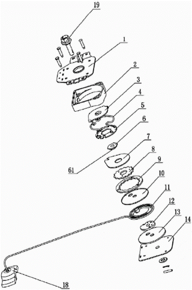
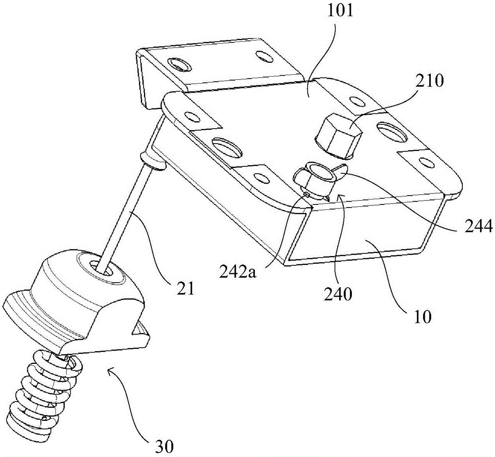
[0037] An embodiment of the present invention provides a spare tire lifter, referring to image 3 , Figure 4 As shown, it includes a housing 10 with an inner cavity 10a, and a lifting mechanism 20 ( Figure 4 ), the lifting mechanism 20 has a pulling member 21 protruding from the housing 10, and one end of the pulling member 21 protruding from the housing 10 is hung with a spare tire fixing member 30, which is stuck in the hub center of the spare tire through the spare tire fixing member 30 hole to fix the spare wheel.

[0038] Continue to refer to Figure 4 , the lifting mechanism 20 has a first rotating shaft 210 and a turntable 220 sleeved outside the first rotating shaft 210, the pulling member 21 is wound on the turntable 220, one...


PUM


Abstract

The invention relates to a spare tire lifter. A lifting mechanism is arranged in an inner cavity of the spare tire lifter, and is provided with a first rotating shaft; the first rotating shaft comprises a first part with larger external diameter and a second part with smaller external diameter; a turntable sleeves the first part; a notch is formed in the second part for containing a boss on the turntable; a traction part of which one end extends out of the shell is wound on the turntable; a first self-locking mechanism comprises an annular groove fixedly formed in the shell and an annular elastic piece arranged in the annular groove; the annular elastic piece is provided with a circumferential opening; the second part is inserted in the annular elastic piece; the annular elastic piece is respectively provided with lugs convexly extending towards the annular inside at the two end parts in the circumferential direction; the lugs are arranged in the notch through clearance fit and are respectively positioned on the two sides of the boss in the circumferential direction. The spare tire lifter provided by the invention has the advantage that a spare tire can be locked through the first self-locking mechanism when a power source suddenly disappears.

Description

technical field [0001] The invention relates to the field of vehicles, in particular to a spare tire lifter. Background technique [0002] The spare tire lifter is a device used to place the spare tire on the vehicle. It is fixed on the outside of the vehicle body and used to lift the spare tire to facilitate the operator to change the tire. [0003] The Chinese patent announced on August 20, 2014 with the announcement number CN203780633U discloses a spare tire lifter, which combines Figure 1 to Figure 2 As shown, the spare tire lifter includes a hollow installation cover plate 1, a housing 2, an eccentric wheel 6, a gear cover plate 7, a gear 8, a ring gear 9, a ring gear bottom plate 10, a steel rope 11, a steel rope fixed wheel 12, Fixed wheel base plate 13, base plate 14, spare tire holder 18, and eccentric wheel driver form, and they are connected as a whole by adjusting bolt 19. The driving part of the eccentric wheel is made up of the upper plate 3 of the driving pa...

Claims


Application Information

Patent Timeline
IPC IPC(8): B62D43/04
Inventor 贾军丁家翔程鹏蒋志伟王寅毅芦勇李岩
Owner SAIC MOTOR
Why Eureka
Try Eureka