Movable pay-off rack with stable tension

A pay-off stand, mobile technology, applied in the direction of conveying filamentous materials, thin material processing, transportation and packaging, etc., can solve the problems of unstable tension, etc., and achieve the effect of constant tension, low cost and simple structure

Pending Publication Date: 2017-03-08
CHANGCHUN LONGYUAN ELECTRIC POWER EQUIP CO LTD
View PDF7 Cites 0 Cited by
  • Summary
  • Abstract
  • Description
  • Claims
  • Application Information

AI Technical Summary

Problems solved by technology

[0004] The invention solves the problem of unstable tension when making coils

Method used


Image

  • Movable pay-off rack with stable tension
  • Movable pay-off rack with stable tension
  • Movable pay-off rack with stable tension

Examples


Embodiment Construction

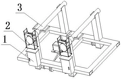
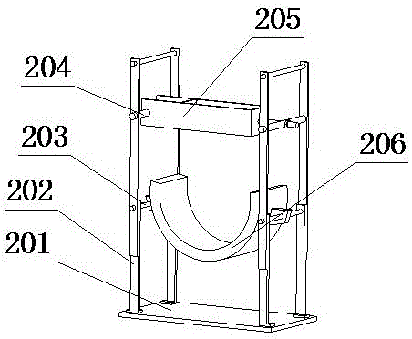
[0010] 1. refer to figure 1 , figure 2 , image 3 , Figure 4 , a movable pay-off frame with stable tension in this embodiment is composed of a vehicle frame 1, a brake device 2 and a support shaft 3, wherein the vehicle frame 1 and the brake device 2 are connected by welding, and the support shaft 3 is connected to the vehicle frame The short rotating shaft 104 in 1 is matched by coaxiality, and rotates with the short rotating shaft 104, energizes the motor 111, controls the positive and negative rotation of the motor through the control cabinet 106, and realizes the movement of the pay-off frame.

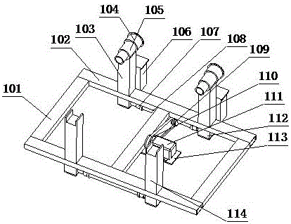
[0011] 2. refer to figure 2 , the frame 1 consists of a longitudinal beam 101, a beam 102, a support rod I 103, a short shaft 104, a sleeve 105, a control cabinet 106, a wheel 107, a wheel shaft 108, a small sprocket 109, a large sprocket 110, a motor 111, and an axle seat 112. The motor support plate 113 and the support rod II 114 are composed of the longitudinal beam 101...


PUM


Abstract

The invention provides a movable pay-off rack with the stable tension. The movable pay-off rack comprises a vehicle frame, a brake device and a supporting shaft; and the vehicle frame is connected with the brake device through welding, the supporting shaft is in coaxiality fit with a short rotating shaft in the vehicle frame, and rotates along with the short rotating shaft, a motor is powered on, the motor is controlled to positively and reversely rotate through a control cabinet, and moving of the pay-off rack is achieved. The problem that when a coil is manufactured, tension is not stable is solved. The movable pay-off rack has the beneficial effects of being simple in structure, constant in provided tension and low in cost.

Description

technical field [0001] The invention relates to a movable pay-off frame with stable tension, which belongs to the field of electric equipment. Background technique [0002] At present, in the process of making coils, a stable tension is required. The tension of the common pay-off frame is tight and loose, and the wire becomes thinner if it is too tight, and the size is out of tolerance when it is loose, causing instability to the product. In view of this, a movable pay-off stand with stable tension is urgently needed in the industry. Contents of the invention [0003] The invention provides a movable pay-off frame with stable tension, which comprises: a vehicle frame 1, a braking device 2 and a supporting shaft 3, wherein the vehicle frame 1 and the braking device 2 are connected by welding, and the supporting shaft 3 is connected to the vehicle The short rotating shaft 104 in the frame 1 is matched by coaxiality, and rotates with the short rotating shaft 104, energizes t...

Claims


Application Information

Patent Timeline
Patent Type & Authority Applications(China)
IPC IPC(8): B65H49/32B65H59/04
Inventor 潘利曹建国杜海陈刚刘世文张邦成庞在祥姜大伟高智柳虹亮常笑鹏
Owner CHANGCHUN LONGYUAN ELECTRIC POWER EQUIP CO LTD
Why Eureka
Try Eureka