Mold locking device for bottle blowing machine

A technology of a clamping device and a bottle blowing machine, which is applied to glass blowing, glass forming, glass manufacturing equipment, etc., can solve the problems of long clamping time and influence on machining accuracy, and achieves requirements for reducing machining accuracy, saving costs, The effect of reducing parts

Pending Publication Date: 2017-03-08
JIANGSU NEWAMSTAR LIQUID PACKAGING ENG TECH RES CENT CO LTD
View PDF5 Cites 1 Cited by
  • Summary
  • Abstract
  • Description
  • Claims
  • Application Information

AI Technical Summary

Problems solved by technology

The existing clamping mechanism, affected by the machining accuracy, takes a relatively long time for clamping the mold

Method used


Image

  • Mold locking device for bottle blowing machine

Examples


Embodiment Construction

[0013] The technical solution of the present invention will be further described below in conjunction with the accompanying drawings.

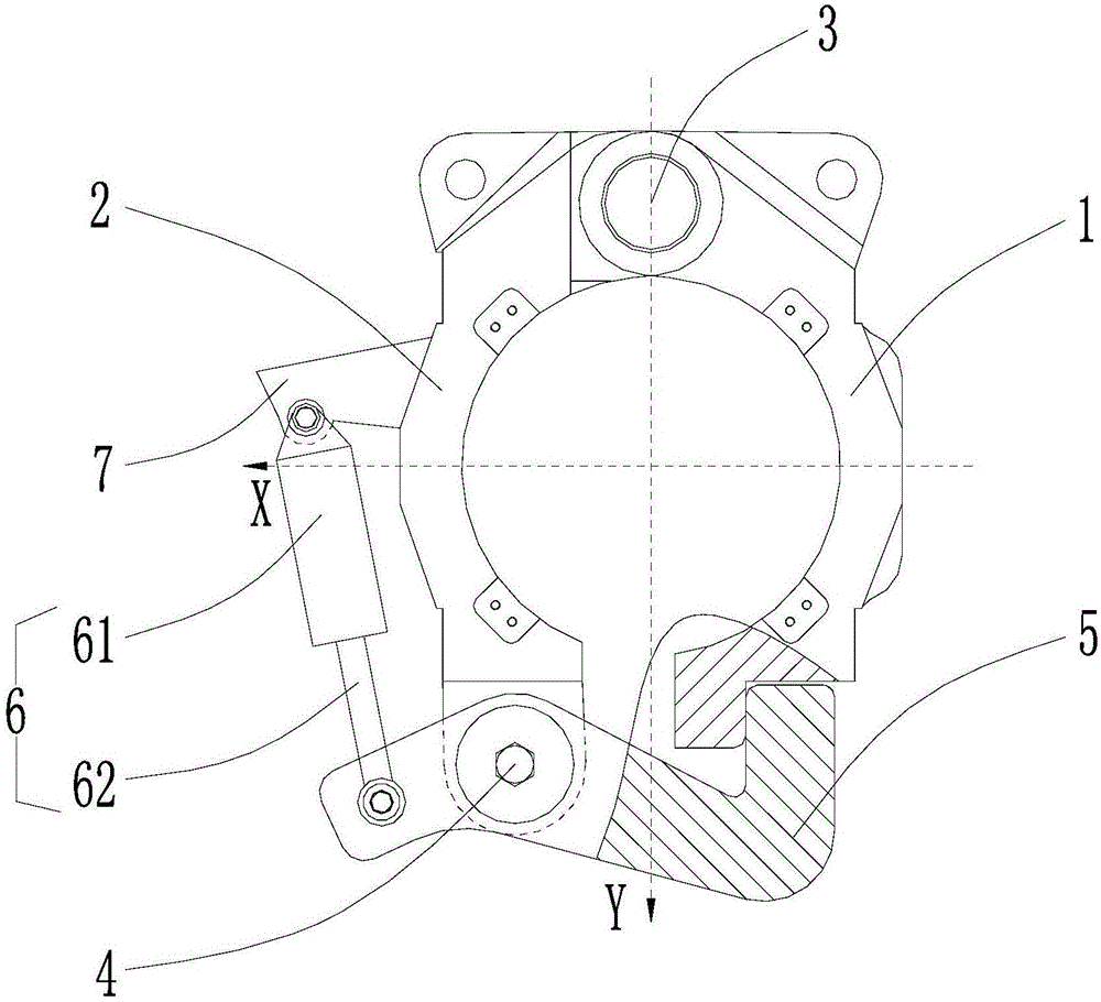
[0014] see figure 1 As shown, the above-mentioned mold clamping device for a blow molding machine, the blow molding machine includes a fixed mold frame 1, which is set at the rear end of the fixed mold frame 1 (the rear end referred to here refers to figure 1 , figure 1 The top in the middle is the rotating shaft of the rear end here), the movable mold frame 2, and the movable mold frame 2 is arranged on the rotating shaft 3 by its rear end rotation, and is used for rotating and cooperating with the fixed mold frame 1 to open and close the mold.

[0015] The clamping device includes a front end located at the movable mold base 2 (the front end referred to here figure 1 , figure 1 The lower part of the center is the front end here), the mold clamping shaft 4, the mold clamping arm 5 sleeved on the mold clamping shaft 4 that rotates around th...


PUM


Abstract

The invention discloses a mold locking device for a bottle blowing machine. The bottle blowing machine comprises a fixed mold base and a movable mold base, wherein one end of the movable mold base is rotatablely arranged on one end of the fixed mold base, and the movable mold base is used for cooperating with the fixed mold base to open or close the mold. The mold locking device comprises a mold locking shaft arranged on the other end of the movable mold base, and a mold locking arm which rotates around the mold locking shaft and is sheathed on the mold locking shaft, wherein one end of the mold locking arm adjacent to the fixed mold base is used for performing collision along the first direction and locking the other end of the fixed mold base. The mold locking device also comprises a driving mechanism which is arranged on the movable mold base and used for driving the mold locking arm to rotate around the mold locking shaft, wherein the driving mechanism is used for driving one end of the mold locking arm to approach or deviate from the other end of the fixed mold base along the line of the second direction so as to lock or unlock the mold; and the first direction is perpendicular to the second direction. By setting the first direction to be perpendicular to the second direction, no matter how huge the power in the first direction is used for opening the mold base, the force component in the second direction is always zero, thereby failing to push the mold locking arm to move; and only one fixed cylinder is needed.

Description

technical field [0001] The invention relates to a mold clamping device for a bottle blowing machine. Background technique [0002] With the development of rotary blow molding machines, the requirements for the production efficiency of blow molding machines are getting higher and higher. Increasing the blowing volume of single mold per hour is the development trend of rotary blow molding machines. In the existing mold locking mechanism, due to the influence of machining accuracy, the time required for mold locking is relatively long. Contents of the invention [0003] The object of the present invention is to provide a mold clamping device for a bottle blowing machine, which has a short mold clamping time and improves the bottle blowing efficiency of the bottle blowing machine. [0004] In order to achieve the above object, the technical scheme adopted in the present invention is: [0005] A mold clamping device for a bottle blowing machine, the bottle blowing machine inc...

Claims


Application Information

Patent Timeline
Patent Type & Authority Applications(China)
IPC IPC(8): C03B9/30
CPCC03B9/30Y02P40/57
Inventor 沈军叶鹏宋文熳
Owner JIANGSU NEWAMSTAR LIQUID PACKAGING ENG TECH RES CENT CO LTD
Why Eureka
Try Eureka