Optical fiber wiredrawing rod hanging mechanism

A technology for wire drawing and optical fiber, which is applied in the field of optical fiber drawing rod hanging mechanism, can solve the problems affecting the temperature change of the drawing furnace, unfavorable fiber drawing quality, and the rod hanging mechanism and the feeding system are not perpendicular to each other, so as to facilitate quality control and improve drawing quality , to ensure the effect of verticality

Active Publication Date: 2017-03-08
GUANGZHOU HONSUN OPTOELECTRONICS
View PDF5 Cites 9 Cited by
  • Summary
  • Abstract
  • Description
  • Claims
  • Application Information

AI Technical Summary

Problems solved by technology

[0003] The traditional optical fiber drawing hanging rod mechanism mainly realizes the cooperation with the feeding system through the simple connection of the threaded rod. Because there is a certain gap between the threaded rod, the connection between the hanging rod mechanism and the feeding system is prone to non-perpendicular phenomenon, which affects the fiber drawing. the quality of
At the same time, the simple fixed connection of the thread is inconvenient to adjust the position of the optical fiber composite rod. If the optical fiber composite rod needs to face the drawing furnace mouth, the position of the drawing furnace needs to be adjusted, and if the adjustment of the position of the drawing furnace is not done properly, it will affect The temperature change to the drawing furnace is not conducive to the quality of optical fiber drawing

Method used


Image

  • Optical fiber wiredrawing rod hanging mechanism
  • Optical fiber wiredrawing rod hanging mechanism
  • Optical fiber wiredrawing rod hanging mechanism

Examples


Embodiment Construction

[0020] The idea, specific structure and technical effects of the present invention will be clearly and completely described below in conjunction with the embodiments and accompanying drawings, so as to fully understand the purpose, features and effects of the present invention. Apparently, the described embodiments are only some of the embodiments of the present invention, rather than all of them. Based on the embodiments of the present invention, other embodiments obtained by those skilled in the art without creative efforts belong to The protection scope of the present invention.

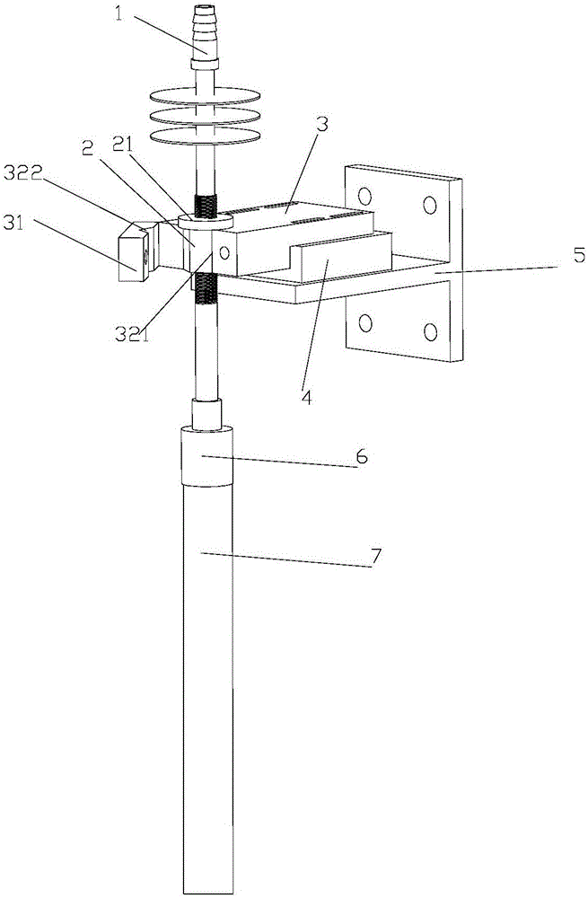
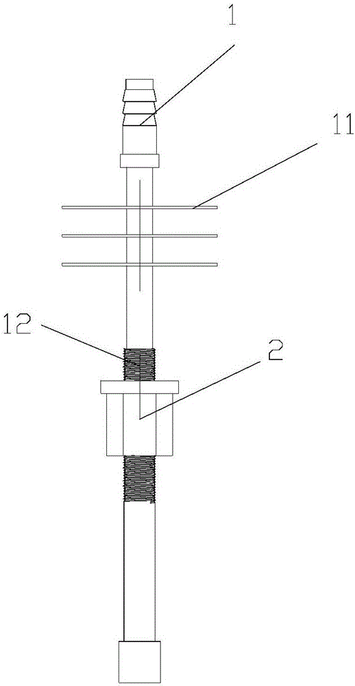
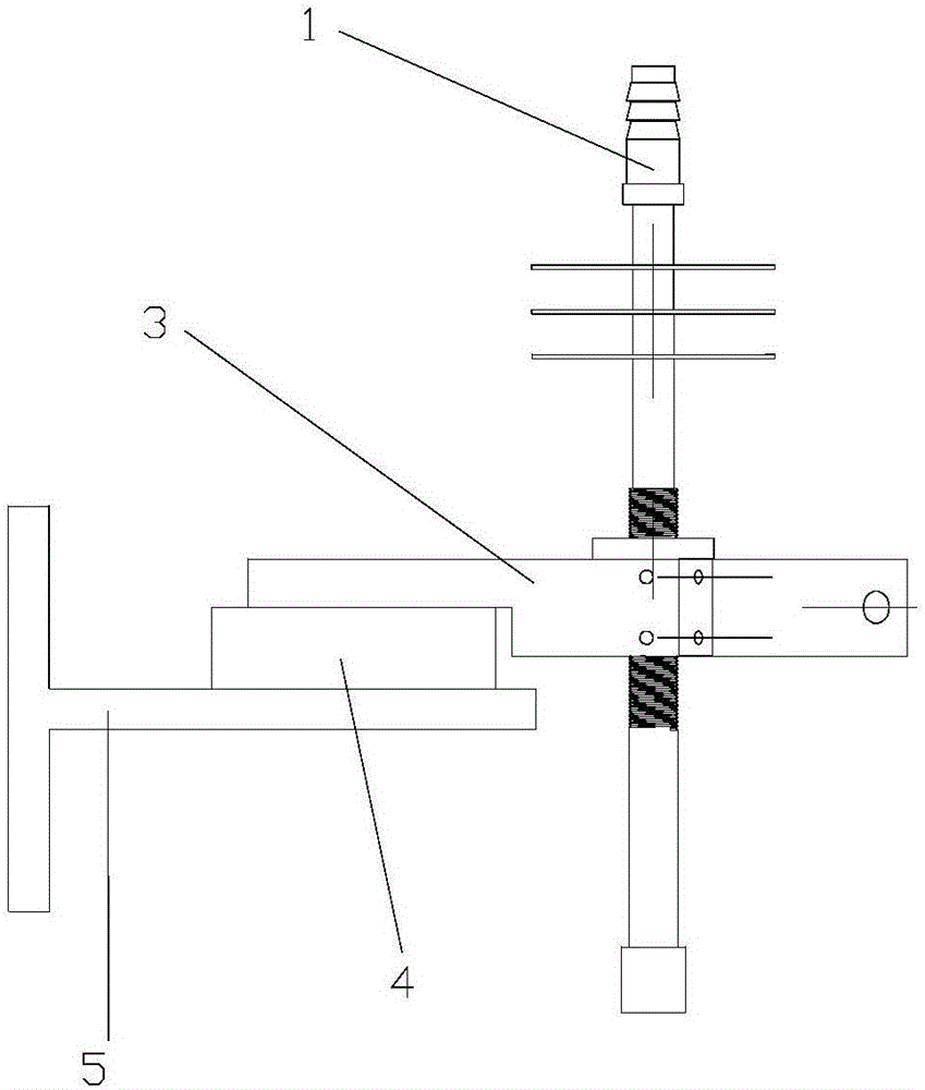
[0021] refer to Figure 1 to Figure 3 , the present invention is a hanging rod mechanism for optical fiber drawing, comprising a hanging rod 1, the hanging rod 1 is arranged on a connecting block 3, a clamping part 2 is arranged on the hanging rod 1, and an opening and closing part 31 is hinged on the connecting block 3 , the connecting block 3 is provided with a clamping groove 1 321, the openin...


PUM


Abstract

The invention discloses an optical fiber wiredrawing rod hanging mechanism which comprises a hanging rod. The hanging rod is arranged on a connecting block. A clamping piece is arranged on the hanging rod. An opening and closing piece is hinged to the connecting block. A first clamping groove is formed in the connecting block. A second clamping groove is formed in the opening and closing piece. The clamping piece is arranged between the first clamping groove and the second clamping groove. When the opening and closing piece is closed, the first clamping groove and the second clamping groove are matched with the outer surface of the clamping piece, and after the opening and closing piece is closed, the clamping piece is fixed to the connecting block through a fixing piece. According to the optical fiber wiredrawing rod hanging mechanism, the clamping piece is arranged on the hanging rod, the clamping piece is clamped when the connecting block is installed and the opening and closing piece is closed, the first clamping groove and the second clamping groove are matched with the outer surface of the clamping piece after the opening and closing piece is closed, close clamping of faces can be achieved, the perpendicularity of the hanging rod is effectively ensured, the optical fiber wiredrawing quality control is promoted, the wiredrawing quality is improved, and the optical fiber wiredrawing rod hanging mechanism is applicable to the field of optical fiber machining.

Description

technical field [0001] The invention relates to the field of optical fiber processing, in particular to an optical fiber drawing rod hanging mechanism. Background technique [0002] At present, optical fiber drawing is to heat and soften a large-diameter glass optical fiber or an optical fiber combination rod, and then draw it into a small-diameter optical fiber filament. During the drawing process, it is necessary to continuously send the fiber composite rod to the high-temperature drawing furnace to keep the lower end of the fiber composite rod in a high-temperature softening state. At the same time, it is necessary to vacuum the fiber composite rod to ensure that the fiber composite rod is bonded after drawing. close. The optical fiber drawing rod hanging mechanism is a mechanism that connects the optical fiber composite rod and the feeding mechanism to realize drawing and sending the optical fiber composite rod to the high temperature drawing furnace at the same time. ...

Claims


Application Information

Patent Timeline
Patent Type & Authority Applications(China)
IPC IPC(8): C03B37/03
CPCC03B37/032
Inventor 徐东骆志财郭清任晓娇黄朋
Owner GUANGZHOU HONSUN OPTOELECTRONICS
Why Eureka
Try Eureka