Blade and rotor type compressor provided with same
A rotor type compressor technology, applied in mechanical equipment, machines/engines, liquid fuel engines, etc., can solve the problems of reduced mechanical efficiency of rotary compressors, failure of reliability of rotary compressors, insufficient lubrication, etc., to achieve Effects of reducing friction loss, improving reliability, and improving performance
- Summary
- Abstract
- Description
- Claims
- Application Information
AI Technical Summary
Problems solved by technology
Method used
Image
Examples
no. 1 example
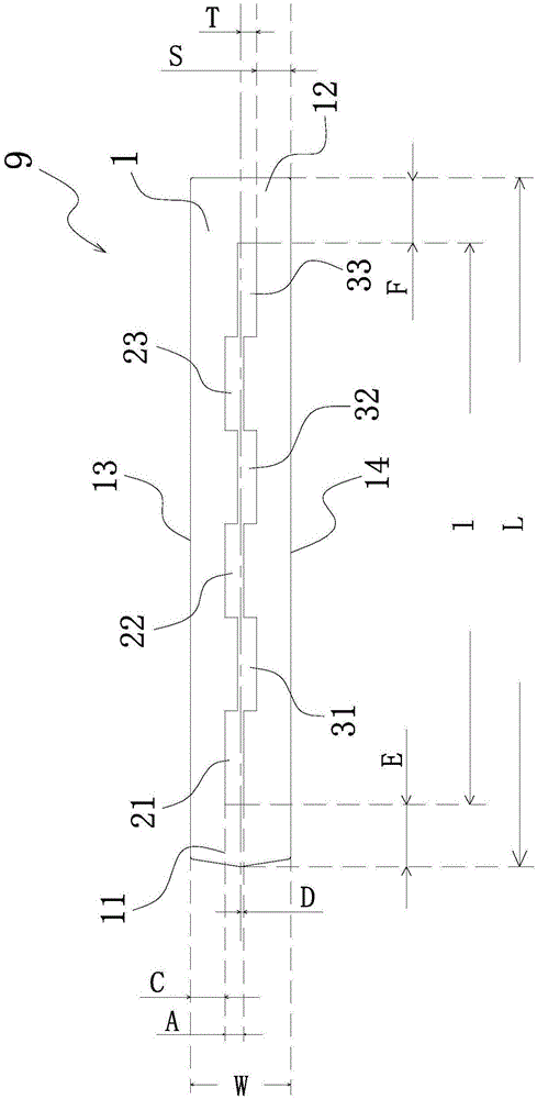
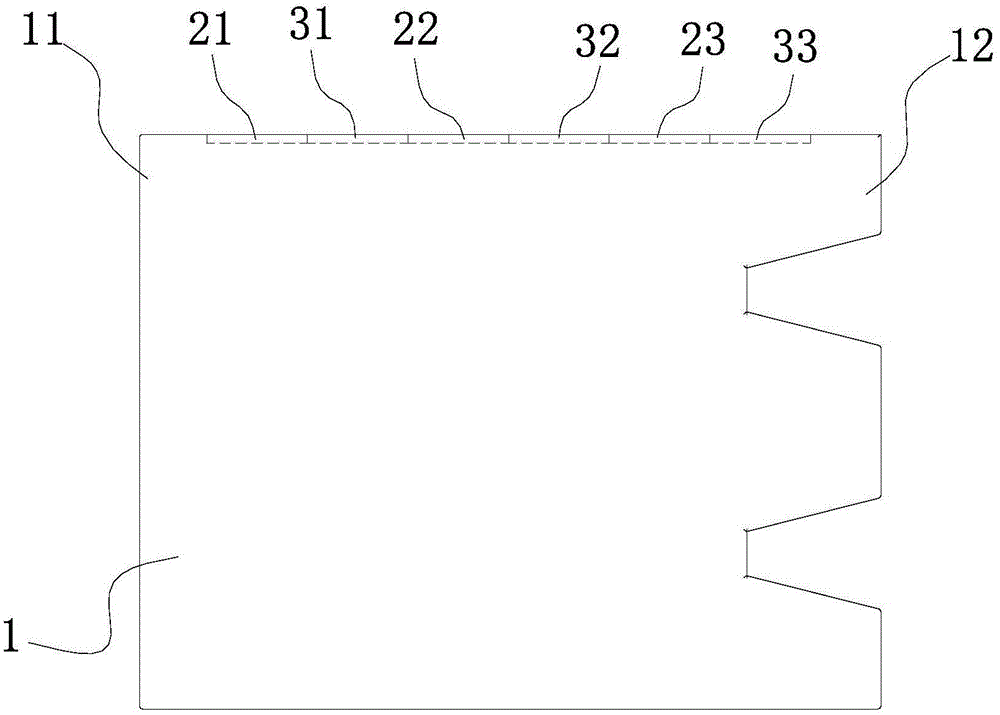
[0047] Please also see Figure 2 to Figure 4 , which respectively show a plan view, a front view and a longitudinal sectional view of the blade of the first embodiment of the present invention. exist Figure 2 to Figure 4 In the preferred embodiment shown, the blade 9 of the present invention includes: a blade body 1 and a groove-type oil storage mechanism. The groove type oil storage mechanism is arranged on the upper end surface and / or the lower end surface of the blade main body 1 . In the embodiment of the present invention, the groove type oil storage mechanism is only arranged on the upper end surface of the blade main body 1, and the figure 2 The upper end surface of the middle blade main body 1 will be described.
[0048] Such as figure 2 As shown, the blade body 1 includes a first end 11 and a second end 12 , and the direction from the first end 11 to the second end 12 is the length direction of the blade body 1 . The blade body also comprises a first side edge...
no. 2 example
[0058] See Image 6 , which shows a top view of a blade of a second embodiment of the present invention. with the above figure 2 The difference from the first embodiment shown in is that the adjacent first oil storage tank and the second oil storage tank are spaced apart from each other. Specifically, as Image 6 As shown, the first oil storage tank 21 and the second oil storage tank 31 are spaced apart along the length direction of the blade main body 1, and the second oil storage tank 31 is spaced apart from the first oil storage tank 22. Similarly, the first oil storage tank 22, The second oil storage tank 32 , the first oil storage tank 23 and the second oil storage tank 33 are all spaced apart from each other. This embodiment can also be implemented and will not be repeated here.
no. 3 example
[0060] See Figure 7 , which shows a top view of a blade of a third embodiment of the present invention. with the above figure 2 The difference from the first embodiment shown in is that the shapes of the first oil storage tank and the second oil storage tank are parallelograms. Specifically, as Figure 7 As shown, the first oil storage tanks 21, 22, 23 and the second oil storage tanks 31, 32, 33 are all in communication with each other. Wherein, the oil storage tanks 21 , 22 , 23 and the second oil storage tanks 31 , 32 , 33 are all parallelograms. It should be noted that the parallelograms mentioned here refer to parallelograms other than rectangles. This embodiment can also be implemented and will not be repeated here.
[0061] other embodiments
[0062] combined with the above Figure 2 to Figure 7 In the illustrated embodiment, it can be understood that the shapes of the oil storage tanks 21 , 22 , 23 and the second oil storage tanks 31 , 32 , 33 can be varied. Fo...
PUM
 Abstract
Description
Claims
Application Information
 - R&D
- Intellectual Property
- Life Sciences
- Materials
- Tech Scout
- Unparalleled Data Quality
- Higher Quality Content
- 60% Fewer Hallucinations
Browse by: Latest US Patents, China's latest patents, Technical Efficacy Thesaurus, Application Domain, Technology Topic, Popular Technical Reports.
© 2025 PatSnap. All rights reserved.Legal|Privacy policy|Modern Slavery Act Transparency Statement|Sitemap|About US| Contact US: help@patsnap.com


